Open source glucose meter shield
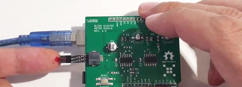
M. Bindhammer won an award for the Assistive Technologies category of the 2016 Hackaday Prize contest for designing an open source Arduino shield that can measure blood glucose level using electrochemical test strips. His glucose meter shield receives the blood sample through a One Touch Ultra test strip and prints out the glucose level on the Arduino IDE serial monitor window.
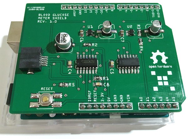
Glucose meter shield
Here is a demo video of the glucose meter shield.
Typically the electrodes are coated such that an enzymatic chemical reaction occurs at the electrode surface and this reaction dictates the resulting current. The details of the electrochemistry can be quite complex. Since commercial strips are used, the details are somewhat unknown as the companies do not release detailed data about their particular test strips operation. Some devices apparently watch the current after a short initial transient (the current will level out to some degree) and then report the current after a fixed time. Another principle looks at the total amount of reaction which has occurred and thus integrates the current with respect to time to obtain the total amount of chemical reaction which has occurred. Our glucose meter will make two measurements to determinate which relates more strongly to the glucose level: one is the current after a fixed time and the other is the total integrated current.