Tag Archives: avr project


Standalone LED tester

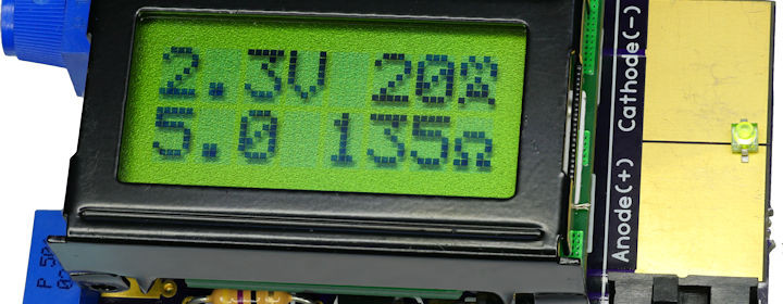
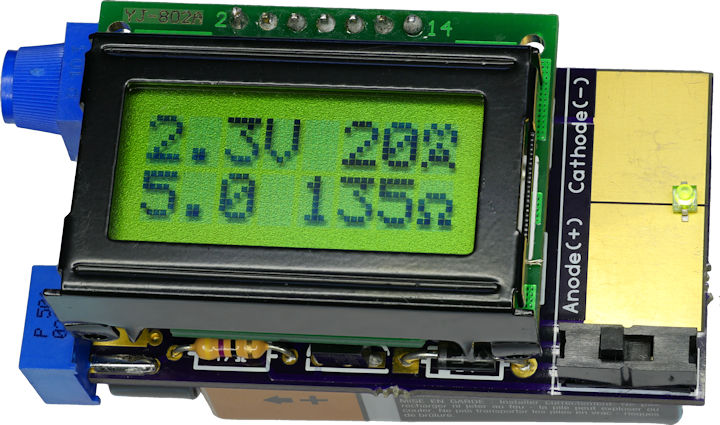
David Cook’s new handy LED tester is based on the LM317L adjustable current regulator and consists of a microcontroller and an LCD to display the forward bias voltage across the LED and required series resistance for operation at the user-specified current and circuit voltage.

DIY LED tester

DIY LED tester

Most projects include at least one LED. Before soldering the LED, how can you determine if the color and brightness meets your needs? After that, how do you calculate the correct value resistor?

Many years ago, I built a handy compact LED testing tool based on the LM317L adjustable current regulator. (You’ll definitely want to click on that link before continuing with this article.) It ended up being one of the most useful tools. In fact, the LED tester sits on a shelf above my keyboard, because I use the tester almost as often as I use my multimeter.

The problem with my original LED test tool is that I need a multimeter to measure the voltage of the LED. And, then I need a spreadsheet to calculate the resistance needed for that LED voltage with a given circuit voltage.

So, I decided to make an improved LED tester with LCD display!

Cellphone controlled car

This cellphone-controlled toy car is controlled over a phone line by sending DTMF tones from another cell or landline phone.

Cell-phone controlled car

Cell-phone controlled car

This Project implements the functionality of IVRS (Interactive Voice Response System) technology.

The car is controlled by a Mobile phone that makes a call to the phone attached to the Car. During the call, if any key is pressed, a DTMF (Dual Tone Multi Frequency) tone corresponding to the key is sent at the other end.

The received tone is processed by the Atmega16 microcontroller with the help of MT8870 DTMF decoder.

The decoder converts the tone into an equivalent binary code before sending it to the controller. The controller is pre-programmed to take a decision for any input and, outputs its decision to the motor driver that drives the car in various directions.

1Hz to 10MHz frequency meter using ATtiny2313

This AVR-based Frequency Meter is capable of measuring frequencies from 1Hz to 10MHz with 1 Hz resolution. The hardware of this project consists of seven 7-segment displays, AVR ATtiny2313 uController, and a few transistors and resistors. The AVR counts input pulses for a precise 1 second  interval (generated using the built-in Timer) and displays the result on the multiplexed seven segment LED displays.

AVR frequency meter


AVR digital clock with white seven segment LED display

This is a digital clock project based on an ATtiny26 microcontroller, displaying time on four seven segment LEDs. The seven segment LEDs glow bright white and are multiplexed through PORTB pins, whereas the segments are driven by PORTA pins. The time is normally shown in hh.mm format but it can be switched to display mm.ss too. The time setting can be done with two push button switches.

Read more

Portable 2.4 GHz Spectrum Analyzer using Atmega8

There are plenty of wireless devices available on the market that broadcast in the 2.4 GHz ISM band. Such devices include Bluetooth, WiFi, Zigbee, wireless USB, cordless phones, wireless mice and keyboards, etc. This project describes a wireless spectrum analyzer to examine the surrounding radio frequencies in 2.4 GHz band.

The project is based on the Cypress’s CYWUSB6935 radio module. It is a complete radio module with PCB trace antenna and it operates in the unlicensed Industrial, Scientific, and Medical (ISM) band (2.4 GHz- 2.483 GHz). The radio module is interfaced with an Atmega8 microcontroller, and the recieved spectrum is displayed on a Nokia 3410 LCD. The microcontroller, the Nokia LCD module and the radio module are all operated at 3.3 V power supply. The firmware is developed in C using AVR GCC for Windows (WinAVR).
Read more