Introduction
Most microcontrollers are equipped with one or more precision timing systems that can be used to perform a variety of precision timer functions including generating events at specific times, determining the duration between two events, or counting events. Example applications that require generating events include generating an accurate 1 Hz signal in a digital watch, keeping a traffic light green for a specific duration, or communicating bits serially between devices at a specific rate, etc.
Theory of operation
The main component of such a timing system is a free running binary counter. The counter increments for each incoming timing pulse. The counter counts continuously from 0 to 2n-1, where n is the number of bits in the counter. Since it runs independently, it can count inputs or clock pulses concurrently while the microcontroller is executing the main program. If the input clock to the binary counter has a fixed known frequency, we can make an accurate measurement of time interval by counting the pulses from the clock. For example, if a particular clock’s frequency is 1 MHz (period 1 µs), and we have counted 3000 pulses on the clock signal, then the elapsed time is 3000 microseconds.
In microcontrollers, the input clock to the internal timing system is software selectable. The microcontroller’s own clock source (which is fixed) can be selected as the clock input to the free running counter module of the timing system. In such a case, the timing system is known to be working as a timer because it is driven by a fixed known frequency clock. However, the input clock to the timing system can also be provided through an external I/O pin of the microcontroller in which case it is known to be working as a counter, and will count the external pulses which may appear at random intervals. These pulses could be manual inputs from a push button, or more likely, would be produced by some other signal source, like a road sensor that generates a pulse every time a car is passed over it.
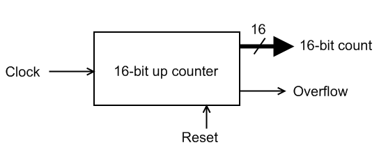
A functional structure of a simple timer module is shown below. This has a free running 16-bit up counter that increments its value on each clock pulse. Thus, the 16-bit output count represents the number of pulses arrived since the counter was last reset to zero. We can convert this value into time interval by knowing the frequency (or period) of the input clock signal.

Suppose, we want to measure the time elapsed between any two successive events. Lets assume that when the first event occurs, the timer is reset to zero, and when the second event occurs, the timer output is 25000. If we know that the input clock has period of 1 µs, then the time elapsed between the two events is 25000×1 µs = 25 milliseconds.
Since this timer’s counter can count from 0-65535 (216-1), this particular arrangement can measure time ranging from 0 to 65535 x 1 µs = 65.535 milliseconds, with a resolution of 1 µs. The maximum time interval a timer can measure is known as the timer’s range, whereas the resolution of a timer defines the minimum interval it can measure.
The timer module has an additional output, overflow flag, that indicates the counter reaches its maximum output, in which case the timer rolls over to 0. In microcontrollers, the built-in timers generate timer overflow interrupts when they roll over back to 0 after reaching their maximum counting range. We can count the number of times the timer overflows, and thus extend the range of time we can measure. In such a case,
elapsed time = (stop count – start count) + number of overflows x (2n-1),
where, n = 16 for a 16-bit counter.
A more advanced timer has a prescaler (shown below). A prescaler is essentially a configurable clock-divider circuit. Depending on the selected configuration bits, the prescaler output could be the same as the input signal, or it may have half the frequency, one-fourth the frequency, one-eighth the frequency, etc. Thus, a prescaler can extend a timer’s range by reducing its resolution. For example, if we use a prescaler to our previous 16-bit timer to divide the clock frequency by 8, then the new range of the timer will be 65535 x 8 µs = 524.280 milliseconds. But the new resolution is reduced to 8 µs.

Timers in microcontrollers have additional configurable features such as enabling or stopping the counter, enabling or disabling interrupt generation when the counter overflows, selecting the clock edge for incrementing the counter, etc.