DIY PICKit 3 programmer/debugger
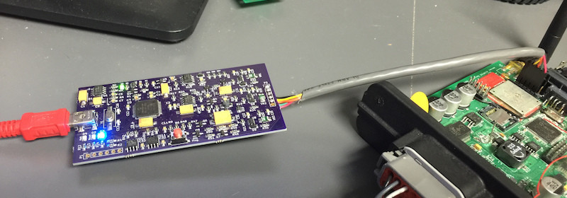
Here’s a detail description from Reviahh on a DIY version of the PICKit 3 programmer/debugger. It uses all SMT components and is portable in size.
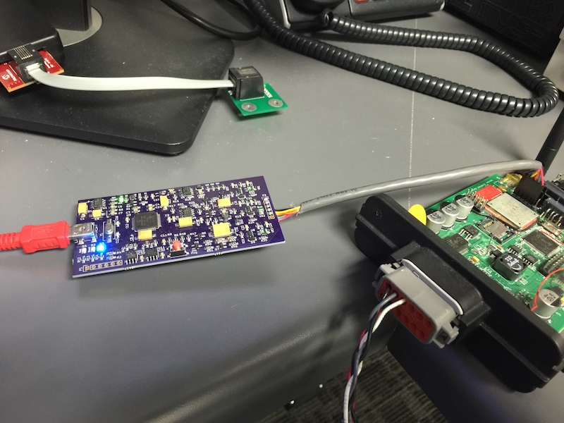
DIY PICKit 3
This schematic is very similar to the one Hendrik used, with a couple component changes and a fix for a PNP transistor that was shown backwards on his schematic. I’ll briefly talk about the different sections that I have labeled above. First – in the upper left corner is the pic24 processor that controls this device. It is a PIC24FJ256GB106 mcu. There are the requisite capacitors and 12MHz crystal attached, as well as a programming header to load its firmware. In addition to these components, the USB connector is shown, as well as the status LEDs and OTG Button connections. Directly below the MCU is the MCP1727 voltage regulator. At the bottom is a LTC4411, a MAX893L, and associated circuitry that among a couple other things, controls the power to the programming target, if it is not self-powered, and this device is supplying power to it. Above that is a MCP601 op-amp and voltage boosting circuitry. In the middle of the page is a MCP1525 voltage reference chip and the Target programming header. Top center you will see the three 74LVC1T45 voltage level shifters, and to the right are the 25LC256 EEPROM and also the SST25VF040B serial flash chip used for the Code image when doing OTG programming.