Tag Archives: ESP8266 project


ESP8266 timer switch

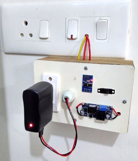
Here are the instructions for building an ESP8266 timer switch for controlling an AC load connected to a wall socket. It uses an ESP-01 module which is programmed to act as a digital ON/Off timer and controls an external relay circuit. The relay circuit must be isolated from the ESP-01 module using an opto-coupler circuit to prevent any electromagnetic interference from the relay coil which may cause reseting of the ESP8266 device.

ESP8266 timer switch for controlling AC load

ESP8266 timer switch for controlling AC load

ESP8266 Weather widget

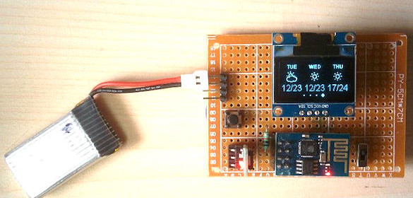
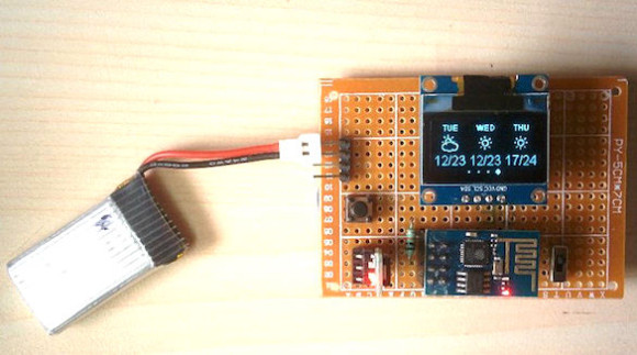
Debasish Dutta‘s Weather Widget uses ESP8266 to retrieve local weather information from web and displays it on a 128×64 OLED Display. The device is capable to display current date, time, and weather information as well as future forecasting for 3 days. The real-time weather data are fetched from the Weather Underground (http://www.wunderground.com) website using an API Key.

ESP8266 Weather Widget

ESP8266 Weather Widget

ESP8266 controls an AC outlet for lamp

Gary shares his ESP8266 controlled on/off switch for a lamp.

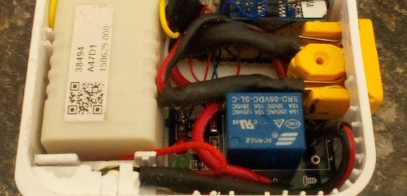
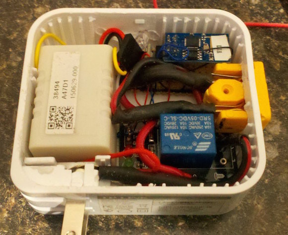
The first step is to find a case to house the parts in. I had an old TP-link router case that I used. It already had a two prong spring out 110v connections but any box will work. When planning your boxes figure out how your going to get the AC in and out of the box. A stop at your local bigbox hardware store should give you lots of idea. At a minimum a deepwall outlet/switch box will work but use your imagination. My project only uses 2 wire as thats what the case supported but if your planning on switching anything other than simple lights use a 3 wire system and include the ground.

If your not sure about what wires goes where take a look online on how you would add a simple manual switch to a circuit and just replace the switch with your device.

On/Off AC outlet switch using ESP8266

On/Off AC outlet switch using ESP8266

IoT enabled lawn mower

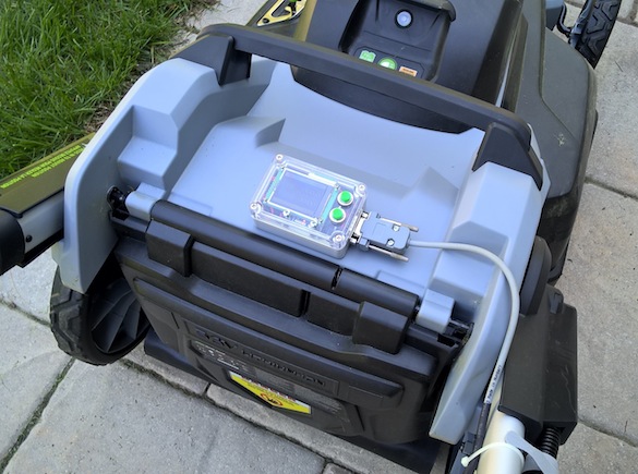
Michel from Quebec, Canada recently bought a EGO brand battery powered lawn mower to which he added an ESP8266 module along with a PIC MCU and a couple of hall sensors to make it an IoT-enabled mowing device that is now capable of sending tweets during its mowing session.

Tweeting lawn mower

IoT enabled lawn mower

To make sure I would not void my mower’s warranty I’ve used 2 Hall Effect sensors and a few magnets: one on the bail switch, five on a wheel. Three revolution of a rear wheel represent a distance of 245cm (~96½”). There are 10 spokes on the back of the wheel. With five magnets this gives me a resolution of 16.33cm (6.43″). The display I’m using is a Digole 160×128 True Color TFT LCD. I like Digole’s displays because they have a backpack with a complete graphic engine and 7 preloaded fonts. The kit run on 2 AAA batteries. The ESP8266 is initialized on power-up to get the actual time on my Windows Home Server and placed to sleep to minimize the power consumption. When it’s time to publish a hard reset is done. At the end of transmission the ESP8266 is put to sleep again.


ESP8266 MP3 decoder

This Github upload shows an example of how to use the I2S module inside the ESP8266 to output sound.

In this case, it is used to output decoded MP3 data (actually, more accurately: MPEG2 layer III data): the code described here basically is a webradio streamer which can connect to an Icecast server, take the MP3 data the server sends out, decode it and output it over the I2S bus to a DAC. The MP3 decoder has been tested for bitrates up to 320KBit/s and sample rates of up to 48KHz.

The biggest part of this code consists of a modified version of libmad, a fixed-point mp3 decoder. The specific version we use here has already been modified by NXP to use less memory (source:www.nxp.com/documents/application_note/AN10583.pdf) and has been massaged by Espressif to store as much constants in flash as possible in order to decrease RAM use even more. The MP3 decoder is fed from a FIFO realized in the external 23LC1024 SPI RAM. This RAM is filled from a network socket in a separate thread.

On the output side, the MP3 samples are fed into the I2S subsystem using DMA. The I2S DMA basically consists of a circular buffer consisting of a number of smaller buffers. As soon as the DMA is done emptying one of the smaller buffers into the I2S subsystem, it will fire an interrupt. This interrupt will put the buffer address in a queue.

When the MP3 decoder has a bunch of samples ready, it will pop a buffer off this queue and put the samples in it until it is full, then take the next buffer etc. The MP3 decoder generally is faster than the I2S output, so at a certain moment there will be no free buffers left. The queue system of FreeRTOS will suspend the mp3 decoding task when that happens, allowing the ESP8266 to attend to other tasks.
« Older Entries Recent Entries »