Tag Archives: GLCD


Lab 20: Interfacing a KS0108 based Graphics LCD (Part 2)
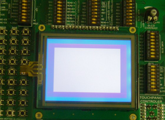
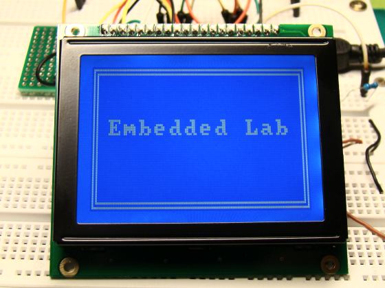
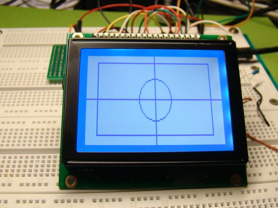
In the first part of this tutorial, we discussed about Winstar’s WDG0151-TMI GLCD module, which is a 128×64 pixel monochromatic display built with KS0108B and KS0107B compatible display controllers. The module was interfaced to a PIC16F887 microcontroller and a test program was written in C to demonstrate how to implement the KS0108 instruction set in the firmware of PIC to activate display pixels on the screen. We wrote our subroutine programs that would turn the GLCD on, move the display location to a specified row and column, and draw a pixel at a given coordinates. You might have realized it by now that how much of effort is required to write the firmware for just plotting a point on a GLCD screen. Today’s discussion will focus more on using the built-in GLCD library routines of mikroC Pro for PIC compiler, which will make your life a lot easier if you are using a graphical LCD in your project.
Using MikroC Pro for PIC GLCD library

Read more

Lab 20: Interfacing a KS0108 based Graphics LCD (Part 1)

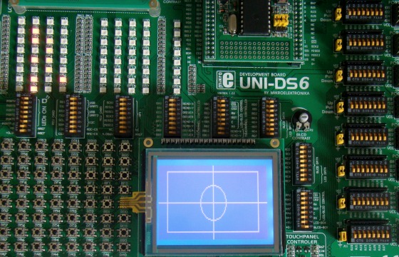
The use of a graphical LCD (GLCD) drastically changes the look of your project. It provides more freedom for presenting data than the HD44870 based character LCDs. Today we will see how to interface a KS0108 (name of the display controller chip) based GLCD to a PIC microcontroller. This experimental tutorial is divided into two parts. In the first part, we will see how to write a firmware for the PIC microcontroller to initialize the GLCD and send data to plot points and lines on the screen. The second part will focus more on exploring the built-in GLCD Library of mikroC Pro for PIC compiler to display more complex texts and objects. Since GLCDs are real resource hungry devices (in terms of required I/O pins and memory), a bigger size PIC microcontroller (PIC16F887, which has 36 I/O pins and 14KB flash memory) is selected for this experiment. I am using MikroElektronika’s UNI-DS6 development board to demonstrate this project, but the circuit setup can also be made on a breadboard.

Interfacing a 128x64 pixels GLCD

Read more

How to use mikroElektronika’s GLCD bitmap editor tool to convert a BMP image in to a data array

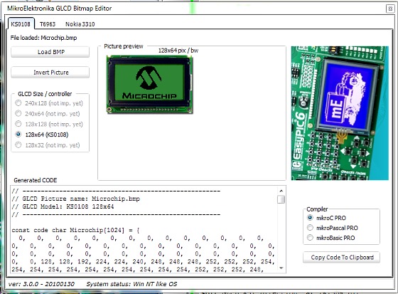
This tutorial describes how to use the mikroElektronika’s GLCD bitmap editor tool to convert a monochromatic bit map (BMP) image file into a data array so that it could be displayed on a graphics LCD using a microcontroller. The GLCD bitmap editor tool is embedded into mikroElektronika’s compilers. It can generate a code equivalent of a BMP image, which can be easily inserted into the microcontroller’s source program.

MikroElektronika's GLCD BMP editor

Read more

PIC microcontroller based audio spectrum analyzer

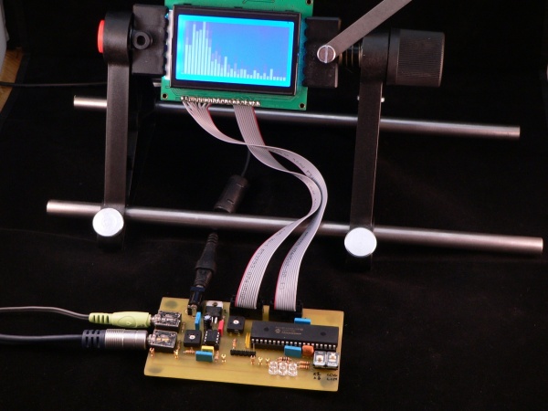
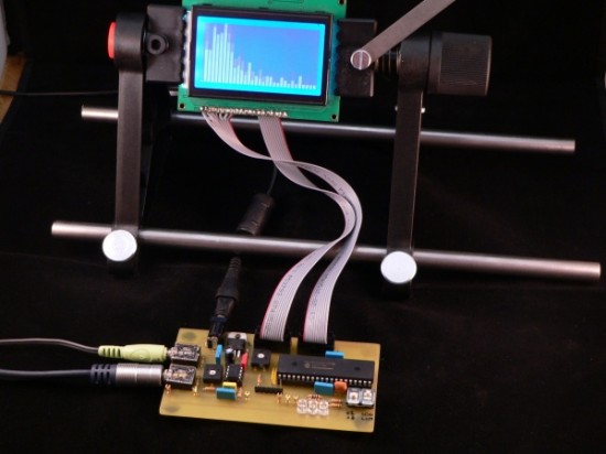
This project introduces a real-time audio spectrum analyzer based on a PIC18F4550 microcontroller. The spectrum frequency analysis is done with a 16-bit Fast Fourier Transformation (FFT) routine coded in C. It uses a 128×64 GLCD to display the FFT waveform of a live audio signal.

“In order to perform a FFT calculation on an audio signal it is necessary to prepare the audio so the PIC18F4550 can sample the signal. The PIC18F4550 provides several analogue to digital converters (ADCs) which can be used to measure a voltage from 0V to 5V with 10-bit accuracy (0-1023). A typical audio line-out signal is an analogue wave with a peak-to-peak intensity of 1V centred around 0V (i.e. it is an AC signal) as shown by the following oscilloscope trace (from pin W2 of the demo board): Read more