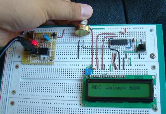
Description
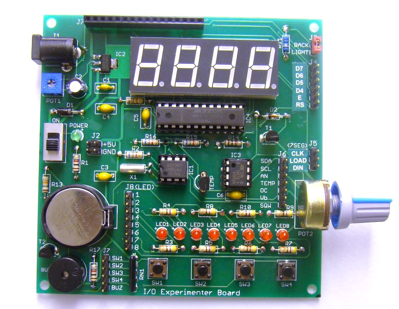
Analog-to-digital conversion (ADC) is necessary because, while embedded systems deal with digital values, their surroundings typically involve many analog signals such as, temperature, speed, pressure, the output of a microphone, etc. They all need to be converted into digital data before being processed by the microcontroller. Today, we will see how to read an external analog signal using a PIC16F688 microcontroller, and display the conversion output (a digital number) on a LCD. The input analog signal will be a varying voltage between 0-5V derived using a potentiometer.
Required Theory
The PIC16F688 microcontroller has a built-in 10-bit ADC with eight input channels. The eight channels are available at RA0, RA1, RA2, RA4, RC0, RC1, RC2, and RC3. They have alternate labels, AN0-AN7, for this function, and are multiplexed into a single Sample and Hold circuit. The output of the Sample and Hold is connected to the input of the A/D converter. The 10-bit conversion result is stored into the ADC result registers ADRESH (A/D Result Higher byte) and ADRESL (A/D Result Lower byte). Each of these registers is 8-bit. The functionality of the A/D module is controlled by three registers: ANSEL, ADCON0, and ADCON1. The details of these control registers are discussed in ADC channels in PIC16F688.
Read more
