Tag Archives: PIC32MX250F128B


Talking multimeter using PIC32 microcontroller

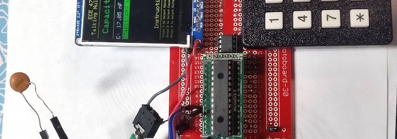
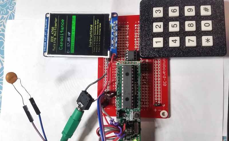
Rachel Dipirro and Jonathan Lo (students of Cornell) built a talking multimeter as their final project for the 2016 Fall ECE 4760 (“Designing with Microcontrollers”) course. Their talking multimeter is powered with the PIC32MX250F128B microcontroller, and it can speak the measured readings while operating as a volt-, ohm-, and capacitance-meter. It is aimed to provide the user these measurements without turning away from the circuit currently being worked on.

Talking multimeter

Talking multimeter

The speaking measurement system will provides an auditory alternative to a visual meter. Our system consists of a TFT LCD to display the reading, a keypad to read user input about the mode of the system, and speakers to hear the readings of both the keypad and the measurements. Key presses on the keyboard determine if the multimeter is used a voltmeter, an ohmeter, or a capacitance meter. Additional circuitry and the functionality on the PIC32MX250F128B is used to map the voltages to ranges acceptable for the MCU and to calculate the parameter values. Capacitance values can be measured between 1pF and 100nF. Resistance values can be measured between 0 and 50kΩ. Voltage values can be measured up to 10V and mapped down appropriately for the MCU using a voltage divider.

RGB LED matrix clock with IR control

Sam Miller and Craig Andres designed a wall-mounted RGB LED matrix clock as their final project for the ECE 4760 course on Designing with Microcontrollers at Cornell. The clock consists of a 32×32 RGB LED matrix, which is controlled using the PIC32MX250F128B microcontroller. The clock also features stopwatch operation and alarm that can be customized through an IR remote. The clock also connects to a PC through a serial interface to synchronize the time with the RTC running on the PC.

RGB clock

RGB LED matrix clock

They write,

Our project runs off of a PIC32MX250F128B microcontroller, which handles all the controls and processing of data for the 32×32 LED Matrix. An Oscillator crystal handles the realtime-keeping component of the clock, and an IR reciever handles the input from our IR Remote Controller. We also have a serial connection to a PC so we can update the time to match the internet-regulated standards that most PCs sync with on a daily basis. All of these components come together to create the LED Matrix Clock we have designed, and we will go into more detail on these below.

The software is the largest part of our project and is almost more of a deliverable than the device itself. We spent a large amount of time creating a standalone library for the LED Matrix display as well as making the project as well broken into logical components as possible. The idea is that anyone can fork our GitHub Repository and easily start customizing the system as they see fit. Towards that goal it was heavy priority to make the project as clean as possible and modular so that in order to changing the use of any component (display being drawn, serial use, rtcc use, IR input, or other) is very simple.