Tag Archives: PWM


Arduino Fan Controller
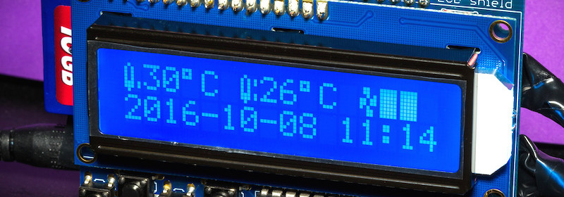
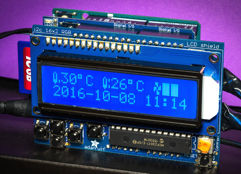
Lucky Resister‘s latest project is about an Arduino-based smart temperature monitor and pulse-width modulation (PWM) Fan Controller. It can simultaneously monitor the ambient temperature using two DHT22 sensors and control the speed of the two fans with minimal noise and at the lowest possible speed that is good enough to maintain the temperature to the desired value. The project also uses Adafruit’s datalogger shield, which contains a real time clock chip and an SD card slot, to record the sensor readings along with time stamps. An I2C LCD provides a nice user interface and displays time, temperature readings, and status of the fans.
Arduino Fan Controller

Arduino Fan Controller

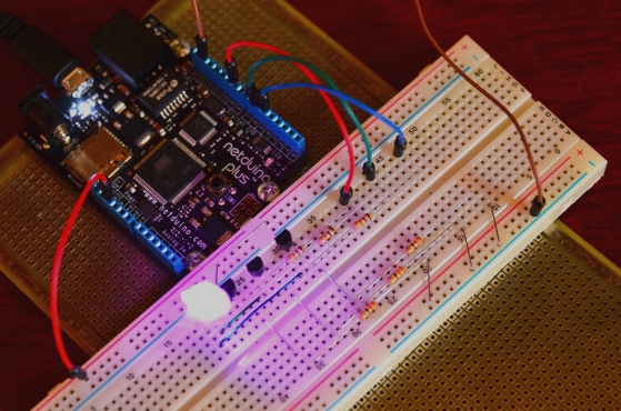
Netduino Day 7 – RGB LED color formation using Pulse Width Modulation

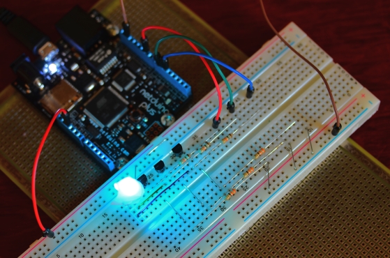
Pulse Width Modulation (PWM) is a digital method of delivering a varying amount of power to a load, and hence can be used to control the brightness of an LED or speed of a DC motor. Controlling the power, we will make this tutorial colorful using a Red Green Blue (RGB) LED. Each segment (lead) of an RGB-LED will get a PWM signal via RgbLed class allowing us to illuminate the RGB-LED with any color defined by RGB. This class can also generate random colors. Using the RgbLed class, some standard colors can also be sent to a RGB-LED.

RGB-LED illuminating a purple color

Read more

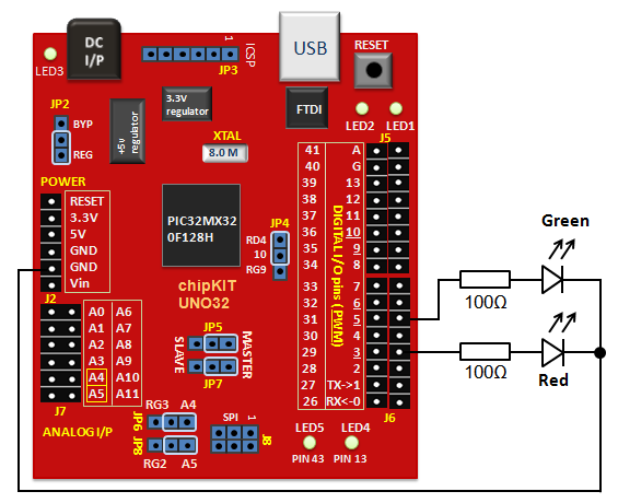
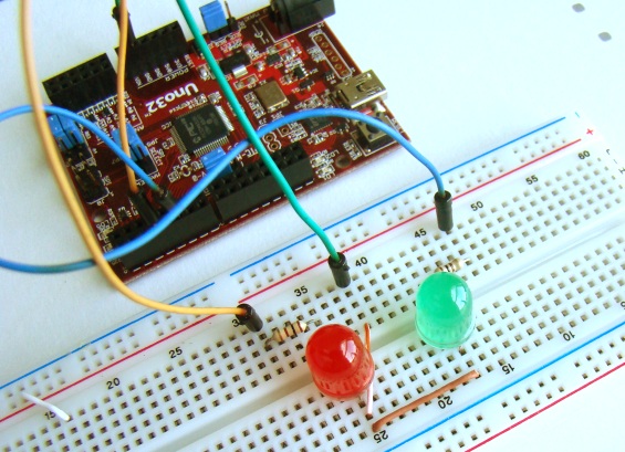
chipKIT Tutorial 5: Pulse width modulation (PWM)

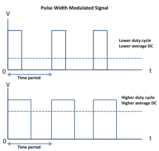
Pulse width modulation (PWM) is a technique of controlling the amount of power delivered to an electronic load using an on-off digital signal. The key idea behind this technique is that the average DC value of the digital signal, and hence the power delivered to the load, can be varied by varying the duty cycle of the signal. This method is commonly used for controlling speeds of DC motors and brightness of lamps. The switching mode power supplies are also based on the PWM technique. In this tutorial, we will discuss about the PWM pins of the chipKIT Uno32 board and illustrate the concept by controlling the brightness of two external LEDs.

PWM

Read more

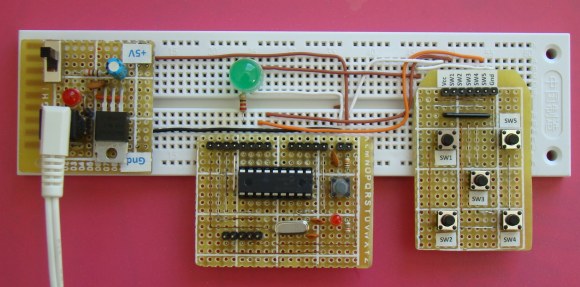
Lab 9: Pulse Width Modulation (PWM) using PIC CCP module

Description

Pulse width modulation (PWM) is a technique of controlling the amount of power delivered to an electronic load using an on-off digital signal. The fraction of the period for which the signal is on is known as the duty cycle. The average DC value of the signal can be varied by varying the duty cycle. The duty cycle can be anywhere between 0 (signal is always off) to 1 (signal is constantly on). Suppose, if the signal has +5 V while it is on and 0 V during off condition, then by changing the duty cycle of the signal, any voltage between 0-5 V can be simulated. This method is commonly used for controlling speeds of DC motors and brightness of lamps. This lab session will talk about how to generate a PWM signal using the PIC16F628A microcontroller and control the brightness of an LED with it. PIC16F628A has a built-in hardware, called Capture/Compare/PWM (CCP) module, to generate a PWM signal.

Read more