16×32 RGB Matrix Panel Driver Shield Revision 1
Our RGB matrix panel driver shield for Arduino Uno has been slightly revised. The shield now also carries the DS1307 RTC chip on board along with a CR1220 coin cell battery holder on the back. It is applicable for driving popular 16×32 RGB matrix panels with HUB75 (8×2 IDC) connectors. Row and column driver circuits are already built on the back side of these matrix panel. The data and control signal pins for driving rows and columns are accessible through the HUB75 connector. It requires 12 digital I/O pins of Arduino Uno for full color control.
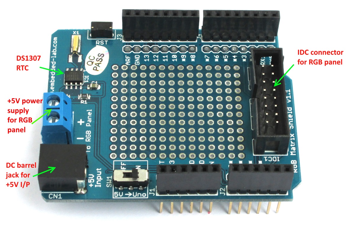
Revised RGB Matrix driver shield
The revised version also has a slide switch (SW1) to select the source of the 5V input to the Arduino Uno. If it is in ON position, the 5V input from the DC barrel jack of the shield also goes to the VIN pin of Arduino Uno. In this case, Arduino Uno does not need to be powered separately as it gets from the shield. If the switch is in OFF position, the Arduino Uno must need its own power supply, which could be from an USB port or an extra DC wall adapter connected to the Uno board.
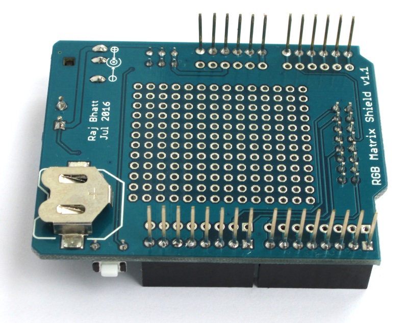
CR1220 coin cell battery holder for RTC chip
We sell the display module, the RGB driver shield, and connecting wires as a kit at our Tindie Store. Outside the United States, you can also purchase it from our Elecrow Store. The DS1307 RTC chip’s I2C bus is pre-wired to the Arduino A4 and A5 pins on the shield. This display module is fully compatible with Adafruit’s RGBMatrixPanel Library.
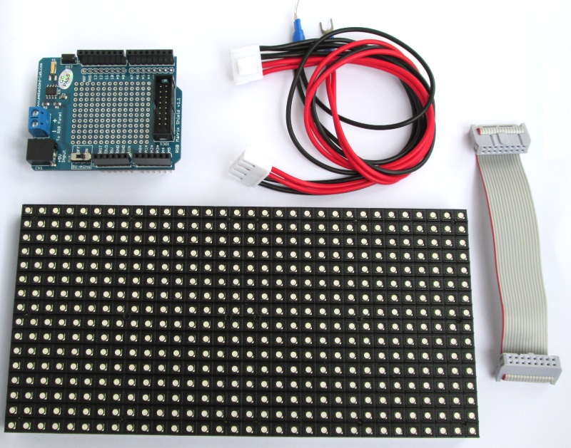
RGB panel and driver shield kit for only $32.99 at our Tindie store
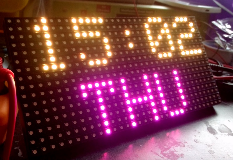
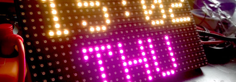
RTC demo
Links:
Buy it here in Unites States
Buy from our Elecrow Store in China
Hookup guide and demo program for this kit
Note that the power supply required to power the LED panel is not included in the kit. You will need a regulated 5V DC power supply with enough current sourcing capability (~2A) to power the RGB panel. More details on the external power supply can be found in the hookup guide (link provided above).