Designing a MPPT solar charger
Solar panels collect energy from the sun and convert it to electricity. Because the sun is not consistent throughout the day, the output power from the solar cell is also not constant. MPPT stands for Maximum Power Point Tracking and is an electronic system for solar panels that allows them to produce and deliver maximum available power. In a solar-powered battery charging system, it is done by varying the ratio between the voltage and current delivered to the battery. For instance, if there is excess power harvested from the panels during high Sun conditions, the MPPT converts it to additional current to charge the battery much faster.
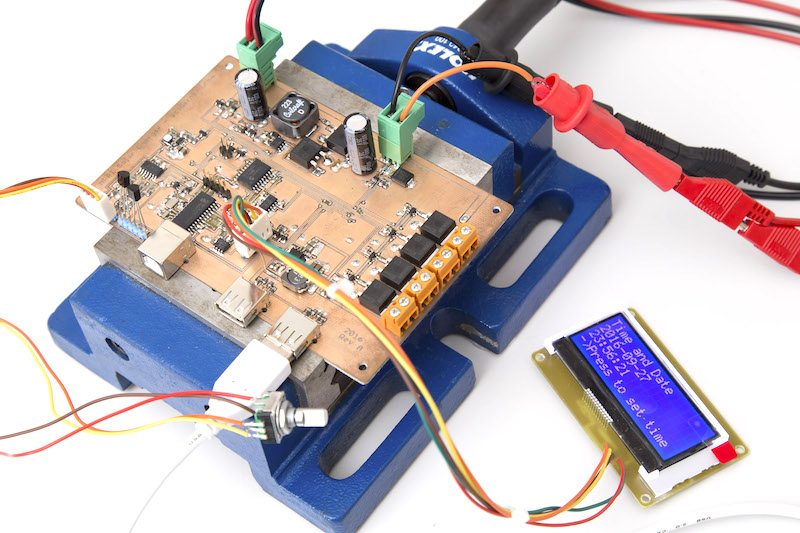
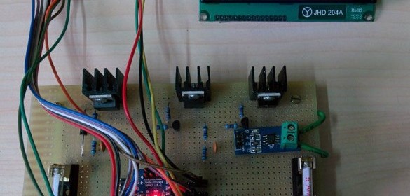
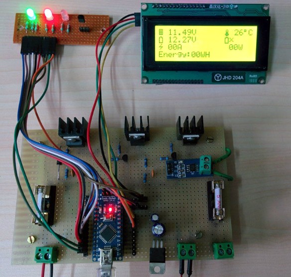
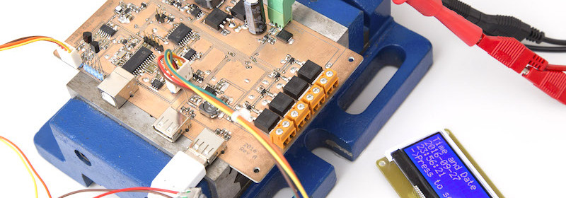
MPPT Solar charger using PIC MCU
LUKAS FÄSSLER shares his design of PIC MCU based MPPT charge controller along with his latest test results. He used a MCP3424 4-channel 18-bit ADC for accurate measurements of the input and output voltages and currents, which are key parameters for tracking the maximum power condition.