Making an Ultrasonic Anemometer

An anemometer is a common instrument at a weather station. It is used to measure the wind speed and wind direction. The most common type of anemometer uses mechanical sensors consisting of three or four hemispherical cups mounted on horizontal arms on a vertical rod. As the wind blows, the cups are pushed causing the arms to rotate at a rate proportional to the wind speed. In addition, a wind vane connected to the anemometer can give the direction measurements. While the cup and vane anemometers are very popular due to their very simple design, they can be susceptible under cold and humid conditions because of their mechanical rotating parts, possibly causing the turbine to stop operating during extreme conditions. Designed without any moving parts, the ultrasonic anemometers are more reliable, maintenance free, long-lasting, and can operate in challenging weather conditions. In this article, we will review the basic working principle of an ultrasonic anemometer, and discuss about some DIY versions of ultrasonic anemometers reported by makers on the internet.
Working principle of ultrasonic wind sensor
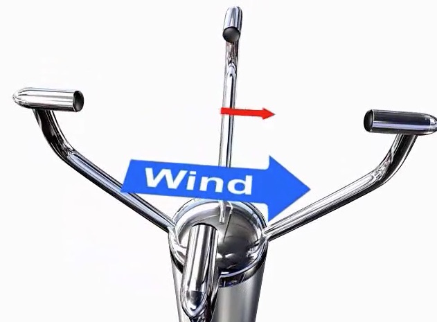
A typical ultrasonic anemometer consists of 2 pairs of ultrasonic transducers mounted at right angles to one another as shown in the figure below. Each sensor is capable to transmit and receive ultrasonic pulses. The physical distance between the opposite facing sensors is fixed and known. During operation, the time taken for an ultrasonic pulse of sound to travel from the North (N) transducer to the South (S) transducer is compared to the time for a pulse to travel from S to N transducer. If there were no wind blowing, the two times should exactly match. Otherwise, the sound wave traveling with the wind should arrive earlier than the sound traveling against it. For example, if there is a wind blowing to N, the N to S travel time would be more compared to the S to N travel time. The difference in the time of flight can give the relative speed of wind along NS axis. Similarly, flight times are also compared along the East-West and West-East directions to compute the wind velocity along the EW axis. The two rectangular velocity components of the wind are then combined to compute the wind vector with a resultant sum and an angle of wind velocity. The sensor arrangement shown below gives only the horizontal wind speed. Measuring a three dimensional wind speed requires sensor arrangements along the vertical direction too.
Basic layout of an ultrasonic anemometer (Source: http://gillinstruments.com/products/anemometer/principleofoperation2.html)
DIY Ultrasonic Wind Sensors
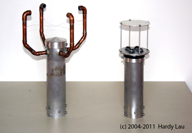
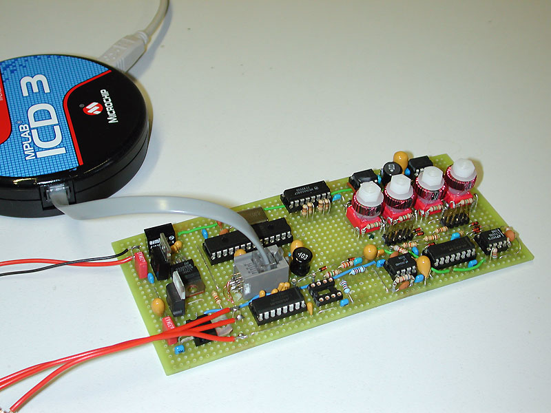
Among hobbyists and DIY community, the cup-based mechanical sensor is the most popular choice for homemade anemometers. There are also a few resources available online to make ultrasonic anemometers. The oldest report that I could find on the internet is from Hardy Lau (Germany). He made two different prototypes of ultrasonic anemometers. His first design consist of four ultrasonic transducers arranged to perform measurements along two orthogonal directions, just like we discussed above. The distance between the opposite transducers is approximately 21 cm. It is capable to measure the horizontal components of the wind speed (up to 45m/sec with a resolution of 0.05m/sec) and the wind direction at 1º resolution. The design implements a heating mechanism utilizing four BD743 power transistors and dummy resistive loads to heat the sensors and the enclosing metallic body during extreme winter conditions to ensure that the sensor operation is not affected by snowfall and possible ice formation. The Microchip dsPIC 30F4012 processor is used to do all the control functions and computation tasks involved in processing the transducer outputs. The wind speed and direction data are available for data logging through a serial interface.
His second prototype is a more advanced and aerodynamically more favorable design with minimum interference with wind, thereby resulting in less turbulence. Opposite facing transducers alternately sends and receive ultrasonic pulses to each other via a top sound reflecting plate, and are processed by the dsPIC33FJ128MC802 processor. For the full detail of the project, visit Hardy Lau’s anemometer page.
Another successful DIY design of an ultrasonic anemometer is from Carl47. His design of the sensor is similar to Hardy Lou’s first version. Carl47 implemented the phase shift method for a precise measurement of the flight times, and uses Atmega328 for processing the sensor data. You can download the full project report from the following link.
https://mysudoku.googlecode.com/files/UltrasonicAnemometer.zip
The most recent design of a DIY ultrasonic anemometer published online is by Lukas Fassler from soldernerd. He has a series of posts about his anemometer project that can be accessed here:
https://soldernerd.com/arduino-ultrasonic-anemometer
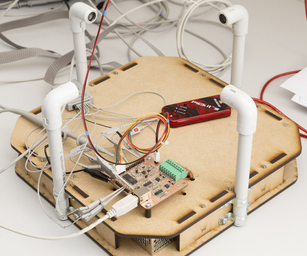
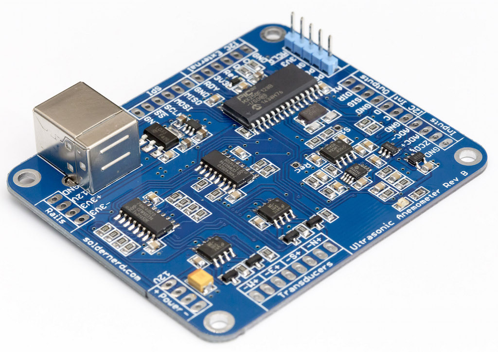
The sensing part is pretty much similar to the earlier two designs we discussed. But Lukas has designed a couple of different varieties of control board for his setup. He has one in the form of an Arduino shield and another one as a standalone board using a PIC32 processor. He even built a tiny wind tunnel using a brushless motor fan for testing his sensor. His series of tutorials on building an ultrasonic anemometer are worth reading.
If you know any other resources on DIY ultrasonic anemometers, please let us know. You can email us at admin (at) embedded-lab.com.
