STM32 Digital-to-Analogue Converter (DAC)
|
|
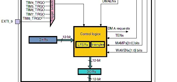
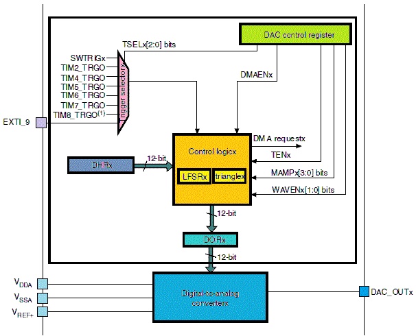
After having played with Analogue-to-Digital Converter (ADC) of STM32 micros, the obvious next internal hardware block to deal with is the Digital-to-Analogue Converter (DAC). As the name suggests this block has just the complementary function of ADC. It converts digital binary values to analogue voltage outputs. The DAC block has several uses including audio generation, waveform generation, etc. Typically in most 8-bit micros, this block is unavailable and its need is somewhat loosely met with Pulse Width Modulation (PWM) block. This is partly because of their relatively less hardware resources and operating speeds. All STM32 micros also have PWM blocks but large capacity STM32s have DAC blocks too. The STM32 DAC block is not very complex and has similarity with the ADC block in terms of operating principle. The simplified block diagram below shows the major components of the STM32 DAC block.
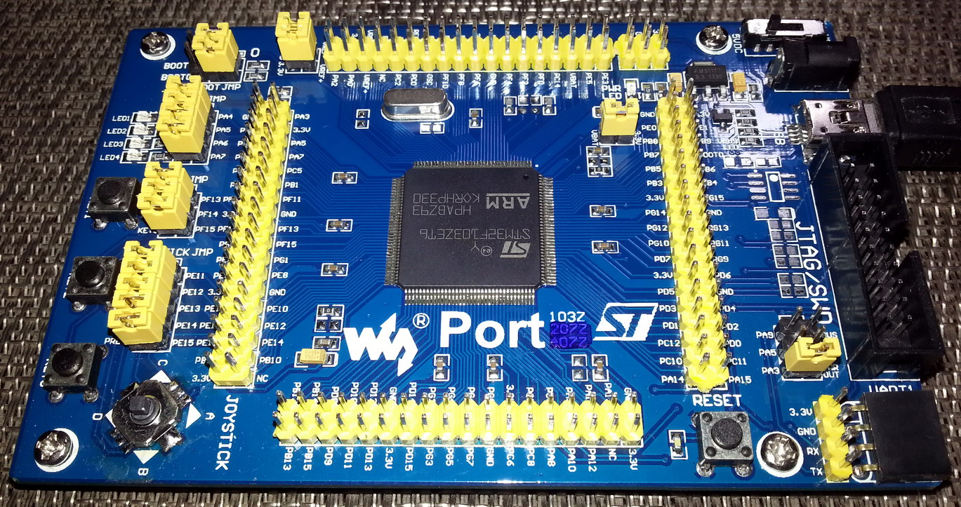
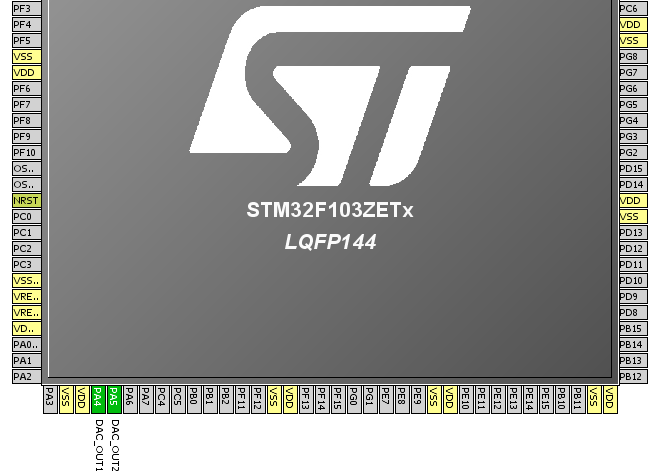
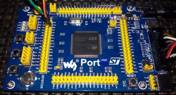
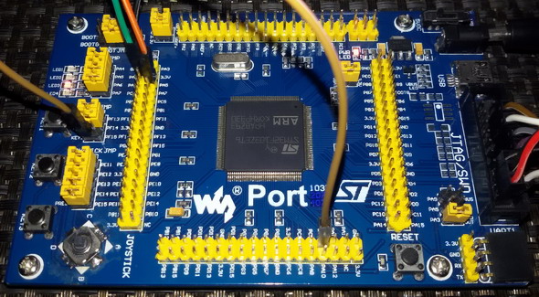
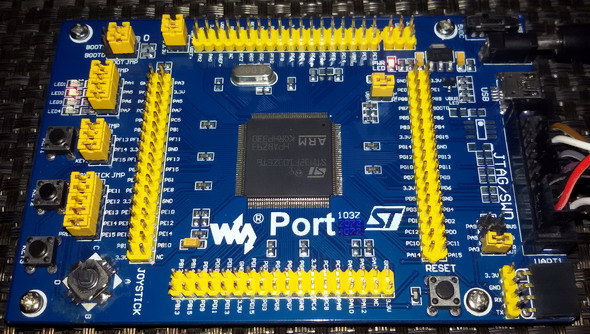
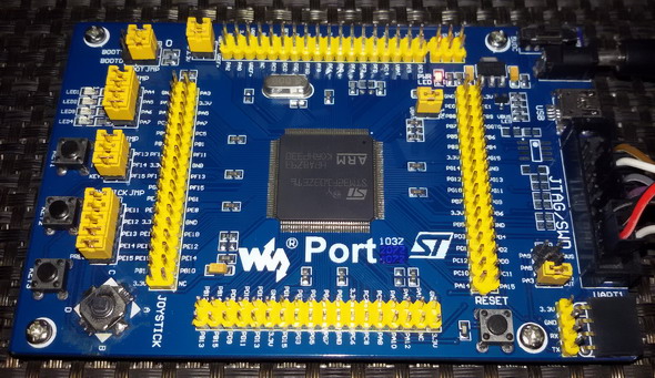
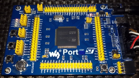
Once again please note that low density STM32 micros do not have any built-in DAC. For this issue I used Waveshare’s Port103Z (http://www.wvshare.com/product/Port103Z.htm) development board featuring STM32F103ZET6 micro. This STM32 micro has two DAC channels with separate converters and packs a great deal of other hardware resources. Most high-end micros like this one comes with at least two DAC channels. Two DAC channels are what is needed for stereo audio generation – a very common DAC-based application. The development board is cleverly designed as such that the DAC outputs are connected to LEDs for directly visualizing the DAC outputs.

Key Feature of STM32 DAC Block
- The DAC block of STM32 micros can be operated in either with 8-bit or 12-bit resolution. The latter has greater precision while the former performs faster than latter.
- Each channel has its own converter and is not dependent on others. In STM32F103ZET6, there are two DAC channel outputs with two separate converters.
- Unlike the DAC of other micros, the DAC of STM32 micros has two additional features and these are pseudo-random noise and triangular waveform generation capabilities. These features aid in signal processing and custom signal generations.
- To enhance precision and control output voltage further, the DAC blocks can be tied with a reference voltage source, usually between 2.4V to 3.3V DC.
- Both left and right justified inputs can be used.
- DA conversion can be event triggered. This feature has lot of applications.
- Just like any other hardware the DAC also has DMA capability.
- The DAC block integrates output buffers that can be used to reduce the output impedance, and to drive external loads directly without having to add an external operational amplifier. Buffering ensures that the original signal is not attenuated or distorted due to loading effects.
- Independent or dual mode of operation possible.
Functional Description
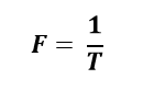
The DAC of STM32 micros can be operated in a number of ways. As stated we can use it in independent and dual mode. Apart from this we can also trigger these DACs with external events. If no triggering option is used, the DAC outputs are updated after one clock cycle. If any triggering option is used, the outputs are updated after 3 – 4 clock cycles. The outputs of the DAC block can be independently or simultaneously updated. The DAC has a maximum resolution of 12-bits. The formula for voltage output from the DAC is as follows:
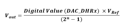
where n is the number of bits.
Unless triggering is used, operating the DAC is pretty easy. We will have to turn on the desired output channel and just write the digital data value. However when it is the other way around, lot of possibilities arise. STM32F10x reference manual states all of these possibilities in dual mode operation section. Though I will not be going to detail all of these operations, the operations are easy.
The outputs can be internally buffered to avoid the need for an external op-amp buffer, thereby reducing both external component count and cost. I highly recommend using internals buffers in order to ensure and maintain accuracy while avoid output loading issues.
The other two toys that come with the STM32 DAC block are the white noise and triangular waveform generator. At first these feature may surprize you or may even make you feel that they are unnecessary. However these stuffs come handy when we need to generate arbitrary waveforms for various applications including music, tones, etc. or inject noise in a signal for debugging. Literally we can simulate a real life noisy electronic circuit environment. The triangular waveform generator can be used to add a variable amplitude triangular waveform component to a given signal. More details here: http://www.st.com/web/en/resource/technical/document/application_note/CD00259245.pdf.
In STM32F103ZET6, the DAC output 1 and 2 pins are located at GPIOA PA4 and PA5 respectively. Though these pins are used as outputs when used with the DAC block, ST recommends that they should be set as analogue inputs to avoid parasitic consumption – an important point to consider.
Registers
In STM32 micros, we just need to deal with three registers – one for configuration, one for selecting software trigger and the other for setting the DAC outputs. We do not have any other register to deal with.
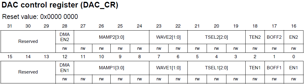
The DAC Control Register (DAC_CR) is the one and only register that we will need to configure the DAC. Configuring this register allows us to enable/disable DAC channels, set output type, enable DMA support and do the other things. Both DACs of STM32 micro are configured using this register alone.
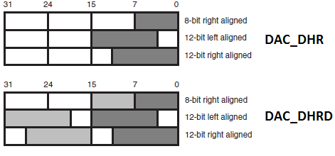
The next set of registers are data registers. These are the places where we will be writing digital data that will be ultimately converted to scaled analogue outputs. The DAC data registers can accept data in three integer formats – 8-bit, 12-bit right aligned and 12-bit left aligned. There are dedicated registers for these. Checkout DAC Data Holding Registers (DAC_DHRx). For dual mode DAC checkout DAC_DHRD registers. Data in DAC_DHRx registers is then loaded to DAC_DORx registers one or several cycles later depending on if any trigger is used or not. The DAC_DORx registers cannot be directly written.
Finally there is a register called DAC software trigger register (DAC_SWTRIGR) for setting up software trigger.
Just like previously we no longer need to deal with registers as I have integrated my version of SPL with the code examples. I would still recommend readers to have a glimpse of them.
Hardware Connection
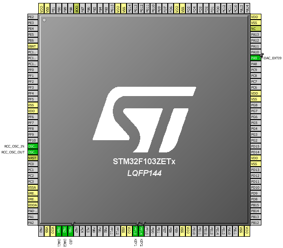
The diagram below outlines the GPIO pins we will be using in the code examples.
Code Examples
Please note that as with any other internal block of the STM32 micro, we need to enable the DAC block’s peripheral clock first then configure desired operations by setting the correct registers and finally enable the required hardware. This is the sequence we should always maintain. Required GPIO port pins should be enabled and configured as recommended prior to setting the DAC itself. Check out the clock configuration I used in all of the examples.

DAC Basic Demo
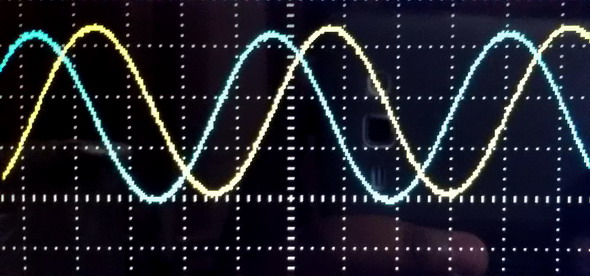
This is the rawest demo of the STM32’s DAC. No triggering is used. The DAC pins output reference-shifted sine and cosine waveforms. Since the DAC’s reference source in my examples is the same as that of the supply (VDD) – 3.3V, the outputs are shifted by 1.65V to cover the entire sinusoidal variation. MikroC’s C Math library is used for the trigonometric function. LEDs connected with DAC output pins fade and glow smoothly, showing a smooth change in voltage across them.
#include "DAC.h"
#include "GPIO.h"
#define radian_per_degree 0.0174532925
void setup();
void GPIO_setup();
void DAC_setup();
void main()
{
signed int temp1 = 0;
signed int temp2 = 0;
unsigned int degree = 0;
setup();
while(1)
{
for(degree = 0; degree < 360; degree++)
{
temp1 = (2047 * cos(radian_per_degree * degree));
temp1 = (2048 - temp1);
DAC_DHR12R1 = ((unsigned int)temp1);
temp2 = (2047 * sin(radian_per_degree * degree));
temp2 = (2048 - temp2);
DAC_DHR12R2 = ((unsigned int)temp2);
delay_ms(6);
}
};
}
void setup()
{
GPIO_setup();
DAC_setup();
}
void GPIO_setup()
{
enable_GPIOA(true);
pin_configure_low(GPIOA_CRL, 4, analog_input);
pin_configure_low(GPIOA_CRL, 5, analog_input);
}
void DAC_setup()
{
enable_DAC(true);
DAC_reset();
set_DAC1_buffer(enable);
set_DAC2_buffer(enable);
enable_DAC1_channel(true);
enable_DAC2_channel(true);
}
Video Link: https://www.youtube.com/watch?v=JW6e-oHBCPQ.
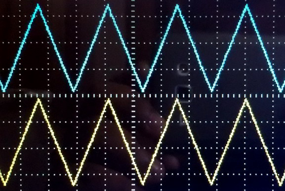
Triangular Waveform Generation
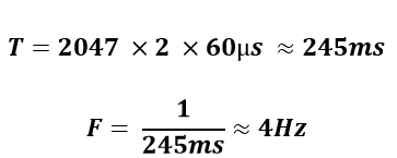
One of the cool and exceptional feature of the STM32 DAC block is its ability to generate symmetrical triangular waveforms. This waveform can be superimposed on other slow waveforms or steady DC signals. There is no need for any wave table or equation for generating the triangular wave. An internal counter takes care of generating the waveform. We can set the amplitude or peak point of the triangle wave as per our need. In order to use triangle waveform, we need to set wave type and triggering options in the DAC_CR register. The frequency of the triangular waveform is dependent on two things – amplitude of the waveform and the frequency of trigger. In case of software trigger, we need to consider delays inside a code. These delays include delay function calls, code execution time and other factors. So far I noticed that the formula below seems to give the approximate time period of the output waveform:
![]()
The 2 in the above equation is due to the fact that the DAC count starts from min or 0 to max amplitude count and then reaches min count in the same way it rose. Thus from the above formula we can deduce frequency of the triangular waveform.
For instance, let us consider a case where we will be using software trigger as such that the trigger is being called every 60µs and the maximum DAC count amplitude is 2047. In this case the time period of the triangular wave is
#include "DAC.h"
#include "GPIO.h"
void setup();
void DAC_setup();
void GPIO_setup();
void main()
{
bit time;
unsigned long peak = Triangle_Amplitude_equal_to_4095;
setup();
while(1)
{
set_DAC1_software_trigger(enable);
set_DAC2_software_trigger(enable);
if(get_input(GPIOF_IDR, 14) == 0)
{
while(get_input(GPIOF_IDR, 14) == 0);
peak++;
if(peak > Triangle_Amplitude_equal_to_4095)
{
peak = Triangle_Amplitude_equal_to_1;
}
enable_DAC1_channel(false);
enable_DAC2_channel(false);
set_DAC1_triangle_waveform_amplitude(peak);
set_DAC2_triangle_waveform_amplitude(peak);
enable_DAC1_channel(true);
enable_DAC2_channel(true);
}
if(get_input(GPIOF_IDR, 13) == 0)
{
while(get_input(GPIOF_IDR, 13) == 0);
time = ~time;
}
switch(time)
{
case 1:
{
delay_us(600);
break;
}
default:
{
delay_us(60);
break;
}
}
};
}
void setup()
{
GPIO_setup();
DAC_setup();
}
void DAC_setup()
{
enable_DAC(true);
DAC_reset();
set_DAC1_buffer(enable);
enable_DAC1_trigger(true);
select_DAC1_trigger_source(Software_trigger);
select_DAC1_wave_type(triangle_wave_generation_enabled);
set_DAC1_triangle_waveform_amplitude(Triangle_Amplitude_equal_to_4095);
enable_DAC1_channel(true);
set_DAC2_buffer(enable);
enable_DAC2_trigger(true);
select_DAC2_trigger_source(Software_trigger);
select_DAC2_wave_type(triangle_wave_generation_enabled);
set_DAC2_triangle_waveform_amplitude(Triangle_Amplitude_equal_to_4095);
enable_DAC2_channel(true);
}
void GPIO_setup()
{
enable_GPIOA(true);
enable_GPIOF(true);
pin_configure_low(GPIOA_CRL, 4, analog_input);
pin_configure_low(GPIOA_CRL, 5, analog_input);
pin_configure_high(GPIOF_CRH, 13, digital_input);
pin_configure_high(GPIOF_CRH, 14, digital_input);
pull_up_enable(GPIOF_ODR, 13);
pull_up_enable(GPIOF_ODR, 14);
}
In this demo we can vary the amplitude of the triangular waveform coming out from both DAC output channels using a button connected to GPIO PF14 pin. A button connected to GPIO PF13 pin can be used to select time period.

Video link: https://www.youtube.com/watch?v=eX3zRjr8bQo.
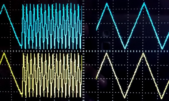
White Noise Generation
The white noise generation module has similar settings as that of the triangular waveform generator. The only thing different apart from waveform is the algorithm that generates white noise. This is not in my scope of explanation. We just need to know that we can use this module to generate variable amplitude pseudo random noise. For better understanding please check this out https://en.wikipedia.org/wiki/Linear_feedback_shift_register. All we need is to mask the LFSR as per our need.
#include "DAC.h"
#include "GPIO.h"
void setup();
void DAC_setup();
void GPIO_setup();
void main()
{
setup();
while(1)
{
set_DAC2_software_trigger(enable);
delay_us(10);
};
}
void setup()
{
GPIO_setup();
DAC_setup();
}
void DAC_setup()
{
enable_DAC(true);
DAC_reset();
set_DAC2_buffer(enable);
enable_DAC2_trigger(enable);
select_DAC2_trigger_source(Software_trigger);
select_DAC2_wave_type(noise_wave_generation_enabled);
set_DAC2_LFSR_mask(0x3FF);
enable_DAC2_channel(true);
}
void GPIO_setup()
{
enable_GPIOA(true);
pin_configure_low(GPIOA_CRL, 5, analog_input);
}


Video link: https://www.youtube.com/watch?v=ylxTQXLa-D4.
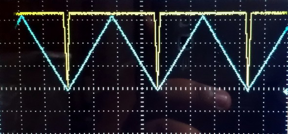
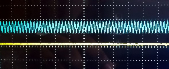
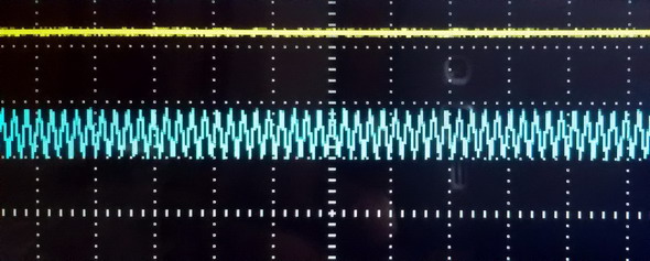
8-bit DAC vs 12-bit DAC
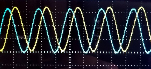
This example is meant to show resolution, speed and precision and their impact. DAC1 is configured as a 12-bit DAC while DAC2 is configured as an 8-bit DAC. I tried to show that for the same output 12-bits resolution will be more precise but it will be slower than less precise 8-bit one. You’ll notice for the same time interval and output, the 8-bit output saturates well before the 12-bit output. If you notice the snapshots, you’ll see that both of these outputs have different slopes and this is where precision and speed comes into play.
#include "DAC.h"
#include "GPIO.h"
void setup();
void GPIO_setup();
void DAC_setup();
void main()
{
signed int temp = 0;
setup();
while(1)
{
for(temp = 0; temp < 4096; temp++)
{
DAC_DHR12R1 = temp;
if((temp > 0) && (temp < 256))
{
DAC_DHR8R2 = temp;
}
delay_us(90);
}
for(temp = 4095; temp > -1; temp--)
{
DAC_DHR12R1 = temp;
if((temp > 0) && (temp < 256))
{
DAC_DHR8R2 = temp;
}
delay_us(90);
}
};
}
void setup()
{
GPIO_setup();
DAC_setup();
}
void GPIO_setup()
{
enable_GPIOA(true);
pin_configure_low(GPIOA_CRL, 4, analog_input);
pin_configure_low(GPIOA_CRL, 5, analog_input);
}
void DAC_setup()
{
enable_DAC(true);
DAC_reset();
set_DAC1_buffer(enable);
set_DAC2_buffer(enable);
enable_DAC1_channel(true);
enable_DAC2_channel(true);
}

Video link: https://www.youtube.com/watch?v=jBfzgFGs7JM.
Dual Mode DAC
Dual mode DAC opens a pathway to a number of possibilities. STM32F10x reference manual discusses various ways of operating the DAC in dual mode. What I felt makes it much simpler. We just need to treat two DAC channels separately. If both DACs have common trigger source then they are said to update simultaneously or synchronously, otherwise they are independent. Both DACs can output same or different waveforms depending on how they are configured.
In this example I configured one DAC to output triangular wave superimposed on a variable DC component while the other DAC is configured to output white noise signal when invoked by an external interrupt on GPIO PA9 pin.
#include "DAC.h"
#include "GPIO.h"
#include "AFIO.h"
#include "Ex_Int.h"
void setup();
void GPIO_setup();
void AFIO_setup();
void DAC_setup();
void ext_int()
iv IVT_INT_EXTI9_5
ics ICS_AUTO
{
if(read_pending_reg(9) != 0)
{
pending_clr(9);
bit_clr(GPIOA_ODR, 6);
delay_ms(200);
bit_set(GPIOA_ODR, 6);
}
}
void main()
{
signed int value = 0;
setup();
while(1)
{
if(get_input(GPIOF_IDR, 13) == 0)
{
delay_ms(10);
value++;
}
if(get_input(GPIOF_IDR, 14) == 0)
{
delay_ms(10);
value--;
}
if(value > 2047)
{
value = 2047;
}
if(value < 0)
{
value = 0;
}
set_DAC1_software_trigger(enable);
DAC_DHR12RD = (((unsigned int)value) | 0x00FF0000);
};
}
void setup()
{
GPIO_setup();
AFIO_setup();
DAC_setup();
}
void GPIO_setup()
{
enable_GPIOA(true);
pin_configure_low(GPIOA_CRL, 4, analog_input);
pin_configure_low(GPIOA_CRL, 5, analog_input);
pin_configure_low(GPIOA_CRL, 6, (output_mode_low_speed | GPIO_PP_output));
enable_GPIOF(true);
pin_configure_high(GPIOF_CRH, 13, digital_input);
pin_configure_high(GPIOF_CRH, 14, digital_input);
pull_up_enable(GPIOF_ODR, 13);
pull_up_enable(GPIOF_ODR, 14);
}
void AFIO_setup()
{
AFIO_enable(true);
pin_configure_high(GPIOA_CRH, 9, digital_input);
pull_up_enable(GPIOA_ODR, 9);
bit_set(GPIOA_ODR, 6);
set_EXTI8_11(9, PA_pin);
falling_edge_selector(9);
interrupt_mask(9);
NVIC_IntEnable(IVT_INT_EXTI9_5);
EnableInterrupts();
}
void DAC_setup()
{
enable_DAC(true);
DAC_reset();
set_DAC1_buffer(enable);
enable_DAC1_trigger(true);
select_DAC1_trigger_source(Software_trigger);
select_DAC1_wave_type(triangle_wave_generation_enabled);
set_DAC1_triangle_waveform_amplitude(Triangle_Amplitude_equal_to_511);
enable_DAC1_channel(true);
set_DAC2_buffer(enable);
enable_DAC2_trigger(true);
select_DAC2_trigger_source(EXTI9_event);
select_DAC2_wave_type(noise_wave_generation_enabled);
set_DAC2_LFSR_mask(0x3AA);
enable_DAC2_channel(true);
DAC_DHR12RD = 0x00FF0000;
}

Video link: https://www.youtube.com/watch?v=2rQQXBaYLMk.
MikroC DAC Library Example
Taking into account that many ARM-based micros have built-in DAC blocks, Mikroelektronika also integrated an easy to use DAC library with MikroC compiler. This library supports most of the functions typically found in a STM32 micro with DAC block and that’s what makes it a code-saver. A few functions as mentioned below are what are needed to configure and use the DAC.
The functions are explained in details in their compiler’s manual and help document.
In my example I also used MikroC’s GPIO library – another useful library for configuring GPIO pins. In this final example I demonstrated a raw use of the DAC. I used two buttons to alternately increase and decrease the brightness of two LEDs connected to DAC outputs.
void setup();
void main()
{
signed int value = 2047;
setup();
while(1)
{
if(GPIOF_IDRbits.IDR13 == 0)
{
value++;
}
if(GPIOF_IDRbits.IDR14 == 0)
{
value--;
}
if(value >= 4095)
{
value = 4095;
}
if(value <= 0)
{
value = 0;
}
DAC1_Ch1_Output(value);
DAC1_Ch2_Output((4095 - value));
delay_ms(1);
};
}
void setup()
{
GPIO_Clk_Enable(&GPIOA_BASE);
GPIO_Clk_Enable(&GPIOF_BASE);
GPIO_Config(&GPIOA_BASE, (_GPIO_PINMASK_4 | _GPIO_PINMASK_5), _GPIO_CFG_MODE_ANALOG);
GPIO_Config(&GPIOF_BASE, (_GPIO_PINMASK_13 | _GPIO_PINMASK_14), (_GPIO_CFG_MODE_INPUT | _GPIO_CFG_PULL_UP));
DAC1_Init(_DAC_DUAL_MODE_ENABLE);
}
Video link: https://www.youtube.com/watch?v=nhgQxpTulhU.
References: STM32F10x Reference Manual.
Happy coding.
Repository: https://github.com/sshahryiar/STM32-Tutorials
Author: Shawon M. Shahryiar
https://www.youtube.com/c/sshahryiar
|
|
Hi Shawon Shahryiar,
Nice article. Currently I am working on STM32F051 controller. My task is to generate DAC tone using PWM. Could you please guide me. if you have any example code, please share me.
Thank you.
What’s DAC tone? What are you trying to use PWM or DAC? As of now my primary focus is towards STM32F10x series MCUs…. The concepts that were shown in these tutorials with STM32F10x series are similar but not 100% same for STM32F0X series MCUs….
radian_per_degree – just what I was looking for!
Thanks
Andy.
This is very helpful. Thank you for sharing… 🙂
Thanks…. 🙂
thanks a lot it save me from going through a whole lot of reading
Most welcome….
Your article is awesome!
Thanks…. 🙂
Pingback: STM32 Digital-to-Analogue Converter (DAC) - Arduino collector blog