Why pay for Serial LCDs when you can make your own?
|
|
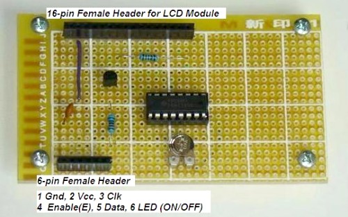
HD44780 based LCD displays are very popular for embedded projects because they are cheap, easy to interface, can display characters, consume power lot less than seven-segment displays, and most of the present day compilers have in-built library routines for them. However, the only disadvantage is that they require at least 6 I/O pins of microcontroller. Well, you may ask, isn’t that less than what seven-segment displays require? Yes, that’s true but there are circumstances where you don’t have left enough pins for LCD display. For example, if you are going to design a temperature sensor based on a PIC12F683 microcontroller, which has just 6 I/O pins, you won’t have pins for interfacing a LCD. One solution for cases like that is to use serial LCD’s. Serial LCD’s available in the market cost more than double of HD44780 based standard one. The serial LCD’s still have the standard LCD module but it has an extra built-in driver module that receives data/command from a host microcontroller in serial format and convert it to appropriate parallel format suitable for HD44780 driver input.
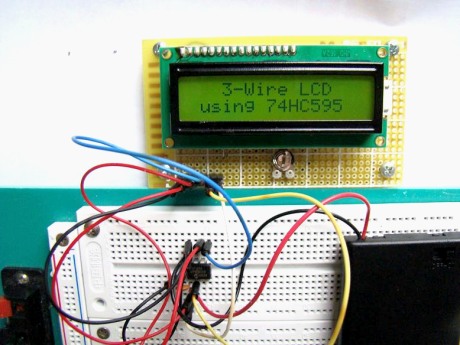
The goal of this project is to show how to make a 3-wire serial LCD driver for low pin-count microcontrollers like PIC12F series using a serial-in parallel-out shift register (74HC595 in this case). PIC12F683 has been chosen here to test the end product. Since 74HC595 is just a shift register with no intelligence of its own, the burden goes to the host microcontroller (PIC12F683) to appropriately transfer the LCD character/command data and control signals in serial format. This part of the intelligence is embedded in the firmware inside PIC12F683. So, a portion of program flash memory inside PIC12F683 is sacrificed for this purpose. The required three pins of PIC12F683 performs following functions.
- Serial data transfer to 74HC595
- Clock signal for the Shift/Storage register
- Enable signal to HD44780 LCD Module
74HC595 Shift Register
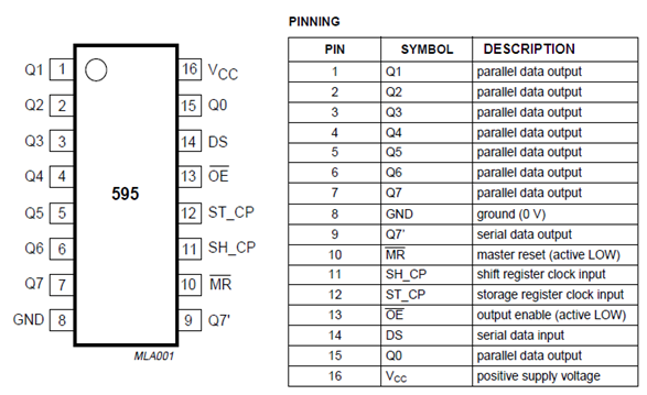
74HC595 is a high-speed 8-bit serial in, serial/parallel-out shift register. It also has a storage register and 3-state outputs. The two registers (shift and stoarge) have separate clocks, SH_CP and ST_CP respectively. Data in the shift register is shifted on the positive-going transitions of SH_CP, and the content of shift register will be transferred to the storage register on a positive-going transition of the ST_CP. If both the clocks are together, the shift register will be one clock ahead of the storage register. The output enable (OE) pin, when pulled Low, enables the 8-bit data of the storage register to show up at the parallel output (Q0-Q7).
HD44780-based character LCD
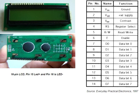
HD44780 based character LCD displays use 14 wire connections: 8 data lines (D0-D7), 3 control lines (RS, E, R/W), and three power lines (Vdd, Vss, Vee). Some LCDs come with backlight features that help reading display data in low illumination conditions. They have two additional connections (LED+ and LED-).
Pin Description
Control pins
The control pin R/W determines if the data transfer between the LCD module and an external microcontroller are actual character data or command/status. When the microcontroller needs to send commands to LCD or to read LCD status, it must be pulled low. Similarly, this must be pulled high if character data is to be sent to and from the LCD module.
The direction of data transfer is controlled by the R/W pin. If it is pulled Low, the commands or character data is written to the LCD module. And, when it is pulled high, the character data or status information from the LCD registers is read. In this project, we will use one way data transfer, i.e., from microcontroller to LCD module, so the R/W pin will be grounded permanently.
The enable pin (E) initiates the actual data transfer. When writing to the LCD display, the data is transferred only on the high to low transition of the E pin.
Power supply pins
LCD module data sheets recommend to use +5V d.c. supply for operation, but some LCDs may work well for a wider range of volatge (3.0 to 5.5 V). The Vdd pin (2) should be connected to the positive power supply and Vss (1) to ground. Pin 3 (Vee) is for display contrast adjusment, which is usually connected to a voltage between 0 and 2V by using a preset potentiometer.
Data pins
Pins 7 to 14 are data lines (D0-D7). Data transfer to and from the display can be achieved either in 8-bit or 4-bit mode. The 8-bit mode uses all eight data lines to transfer a byte, whereas, in 4-bit mode, a byte is transferred as two 4-bit nibbles. In the later case, only the upper 4 data lines (D4-D7) are used. This technique is beneficial as this saves some input/output pins of microcontroller.
For further details on LCDs, it is recommended to read these two articles from Everyday Practical Electronics magazine : How to use intelligent LCDs
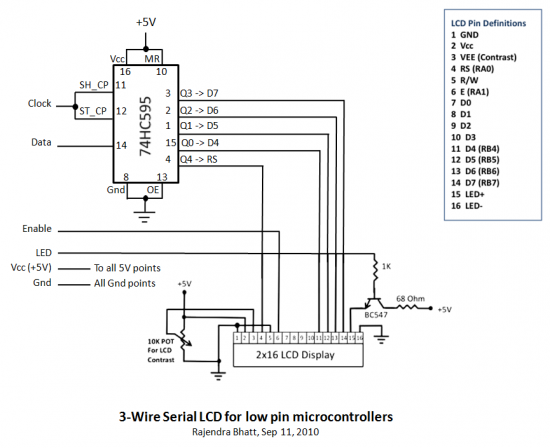
Part 2. http://lcd-linux.sourceforge.net/pdfdocs/lcd2.pdfCircuit Diagram
While using these routines, at the beginning of your program, the Data_Pin, Clk_Pin, and Enable_Pin variables must be defined to the proper microcontroller ports used in the circuit. The test circuit given here uses GP1 of PIC12F683 as Clk_Pin, GP5 as Data_Pin, and GP2 as Enable_Pin. Two blinking character strings, Message1 and Message2, are displayed at different locations on LCD using these routines.
Note: PIC12F683 Settings
Clock, Data, and Enable lines are served through GP1, GP5, and GP2 ports.
 /* 3-wire Serial LCD using 74HC595
    Rajendra Bhatt, Sep 6, 2010 */

sbit Data_Pin at GP5_bit;
sbit Clk_Pin at GP1_bit;
sbit Enable_Pin at GP2_bit;

// Always mention this definition statement
unsigned short Low_Nibble, High_Nibble, p, q,  Mask, N,t, RS, Flag, temp;

void Delay_50ms(){
 Delay_ms(50);
}

void Write_LCD_Nibble(unsigned short N){
 Enable_Pin = 0;
 // ****** Write RS *********
 Clk_Pin = 0;
 Data_Pin = RS;
 Clk_Pin = 1;
 Clk_Pin = 0;
 // ****** End RS Write

 // Shift in 4 bits
 Mask = 8;
  for (t=0; t<4; t++){
   Flag = N & Mask;
   if(Flag==0) Data_Pin = 0;
   else Data_Pin = 1;
   Clk_Pin = 1;
   Clk_Pin = 0;
   Mask = Mask >> 1;
  }
  // One more clock because SC and ST clks are tied
  Clk_Pin = 1;
  Clk_Pin = 0;
  Data_Pin = 0;
  Enable_Pin = 1;
  Enable_Pin = 0;
}
// ******* Write Nibble Ends

 void Write_LCD_Data(unsigned short D){
 RS = 1; // It is Data, not command
 Low_Nibble = D & 15;
 High_Nibble = D/16;
 Write_LCD_Nibble(High_Nibble);
 Write_LCD_Nibble(Low_Nibble);
 }

void Write_LCD_Cmd(unsigned short C){
 RS = 0; // It is command, not data
 Low_Nibble = C & 15;
 High_Nibble = C/16;
 Write_LCD_Nibble(High_Nibble);
 Write_LCD_Nibble(Low_Nibble);
}

void Initialize_LCD(){
 Delay_50ms();
 Write_LCD_Cmd(0x20); // Wake-Up Sequence
 Delay_50ms();
 Write_LCD_Cmd(0x20);
 Delay_50ms();
 Write_LCD_Cmd(0x20);
 Delay_50ms();
 Write_LCD_Cmd(0x28); // 4-bits, 2 lines, 5x7 font
 Delay_50ms();
 Write_LCD_Cmd(0x0C); // Display ON, No cursors
 Delay_50ms();
 Write_LCD_Cmd(0x06); // Entry mode- Auto-increment, No Display shifting
 Delay_50ms();
 Write_LCD_Cmd(0x01);
 Delay_50ms();
}

void Position_LCD(unsigned short x, unsigned short y){
 temp = 127 + y;
 if (x == 2) temp = temp + 64;
 Write_LCD_Cmd(temp);
}

void Write_LCD_Text(char *StrData){
 q = strlen(StrData);
 for (p = 0; p<q; p++){
  temp = StrData[p];
  Write_LCD_Data(temp);
 }

}

char Message1[] = "3-Wire LCD";
char Message2[] = "using 74HC595";

void main() {
CMCON0 = 7;  // Disable Comparators
TRISIO = 0b00001000;  // All Outputs except GP3
ANSEL = 0x00; // No analog i/p

Initialize_LCD();

do {
 Position_LCD(1,4);
 Write_LCD_Text(Message1);
 Position_LCD(2,2);
 Write_LCD_Text(Message2);
 Delay_ms(1500);
 Write_LCD_Cmd(0x01);  // Clear LCD
 delay_ms(1000);
} while(1);

}
- How to use Intelligent Liquid Crystal Displays, by Julyan Ilett, (February, March 1997 EPE)
- Two-wire LCD:ATM18 display for the Elektor AVR Project, by Jurss and Rudolph, (elektor -5/2008)
|
|



Interesting educative project, but I have a different idea, is this project idea can work in opposite way? for example, i’m looking for a way how to take parallel data from a PIC going to 1×16 LCD and turn it to serial data so that I can use it for a 7 segment LED board that has serial input ? is it possible ?
Thanks
I, too am trying to achieve this. Have you made any progress in your endeavors?
do you know of any way of running this using an arduino?
If you eliminate the LED control you can do this with 2 wires. I made a 3-wire, shift register interface that has simpler code because it does a full 8-bit interface to the 1602 LCD. It uses the 74HC164 shift register which does not require an extra clock to latch after doing the shift like the HC595 does. It does not include LED control but that isn’t important for my applications. Simple assembly code for the 12F683 that allows the clock line to also control the register select of the LCD.
I agree, great project indeed. Just it didn’t work on my AVR(Easy AVR). I have used WH1602b 16×2 cheap display from WinStar, re-wrote source to adopt port pins for tiny44, but, LCD was displaying garbage data.. I assumed it is timing issue, and found that it is critical to let some time Enable bit left HIGH (50µs worked for me) at the end of “Write_LCD_Nibble” before switch to low.
This, like all the projects here are just great! Very well documented.
I wonder though about the rationale behind this project, Making your own serial LCDs. If you have to add a 16 pin chip, the 74HC595 shift register to an 8 pin PIC, then write 2 pages of code to control it, then what’s the point? I would just use a 16F88 or similar, and write directly to the 4 bit LCD, using the 6 lines you mention. Why take up valuable real estate with an 8 pin and 16 pin chip (24 pins total) and have the hassles of connecting, troubleshooting, writing code to make it all work. With a 16F88, 18 pins total, and PicBasic Pro I can write to an LCD with 6 setup commands and two single-line instructions to write two lines on the LCD. I believe in the KISS principle: Keep it Simple. I could only see the use of this if the PIC was not on the same board (or within 3 feet) of the LCD. (But then the shift register would have to be on the board with the LCD.)
Pingback: vulussu» Blog Archive » 3-wire lcd with 74HC595
Do you hex code of the same pls? I am AVR guy hence not aware fully with PIC programming and not having any IDE so.
Regards,
Pradip
I figured out what is missing:
void Write_LCD_Text(char *StrData){
q = strlen(StrData);
for (p = 0; p<q; p++){
temp = StrData[p];
Write_LCD_Data(temp);
..maybe you should update it in your code.
P.S.
How to modify code to work on 20×2 LCD display?
@micro,
You are right. Something went wrong while copying and pasting the code. I have corrected it now.
It should work for 20×2 LCD too without any changes. Did you try?
for (p = 0; p
temp = StrData[p];
Write_LCD_Data(temp);
}
something is missing here?
Pingback: I2C LCD help
Pingback: ???????? ??????????? Urd | RepRap-??????
I typo-ed the schematic link tags.
Schematic
https://picasaweb.google.com/lh/photo/-vQWBARseWkgd6NId1qwMrxgn5Wcuni7bDfJrIdyGSM?feat=directlink
Hey Rick,
Thank you for sharing the diagram. I understand what you are saying, we can save one more pin by this method, and we should make sure that the output of shift register connected to the cathode of diode is always high while generating the E pulse. We can do that by shifting an extra 1 at the beginning of any 4 bit LCD data or command.
You can save one wire of the microcontroller interface by using an output on the shift-register wire-or’ed with the clock to drive the LCD Enable pin. I found this idea years ago, so unfortunately I can’t remember where.
See: .
Very well documented – I love it!
Pingback: Shift register is all it takes to make a 3-wire serial LCD | House of Mods
Pingback: Shift register is all it takes to make a 3-wire serial LCD « Black Hat Security
Pingback: Shift register is all it takes to make a 3-wire serial LCD - Hack a Day