Voltage monitor for car’s battery and its charging system
|
|
My 2010 Equinox has got every feature that a modern automobile should have. However, one thing that I personally find missing is the real-time monitoring of voltage across the car’s battery terminals. This may not seem to be that important but one of the most common reasons for a car battery failure is the faulty charging system. If the charging system is not working properly, the battery will not get the proper charging voltage (about 13.8 V for 12V battery) across its terminals and it could go flat. This project is about making a simple electronic voltage monitor system for car’s battery and its charging system. It plugs into the car’s cigarette lighter receptacle and displays the instantaneous output voltage across the battery terminals on a 4-digit seven segment LED display. This helps you to get early warnings for possible battery and its charging system problems. Microchip’s PIC16F1827 is the main controller in this project, which uses the built-in Fixed Reference Voltage (FVR) module to achieve a very precise and accurate A/D conversion of the battery voltage.

Car's battery and charging system voltage monitoring device
Theory
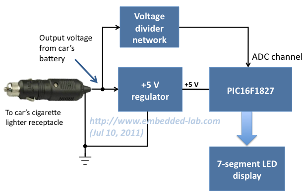
As I said this project is simply about making a precise digital voltmeter that plugs in to the car’s cigarette lighter receptacle and displays the instantaneous voltage across the battery terminals. When the engine is turned off, the voltage measured by this device is the actual output voltage from the battery. However, if the engine is on or the car is running, it actually measures the charging voltage across the battery that is coming from the car’s charging system (alternator + rectifier). The functional block diagram of this project is shown below.

Functional block diagram of car battery monitor system
The +5V power supply for the PIC16F1827 microcontroller circuit is derived from the car’s battery output voltage (usually +12V) using a regulator IC (such as LM7805). The battery terminal voltage is measured through an ADC channel of PIC16F1827. The FVR module inside PIC16F1827 is chosen to derive a stable positive reference voltage of 4.096 V for precise A/D conversion. Before feeding to the ADC channel, the battery output voltage is scaled down to below the reference voltage by using a voltage divider network. The measured instantaneous battery voltage is shown on a 4-digit seven segment LED display.
Read my previous article, Using Fixed Voltage Reference (FVR) for A/D conversion in enhanced mid-range PIC microcontroller, to find more information on the FVR module of PIC16F1827.
Circuit diagram
The circuit diagram of this project is shown below. The PIC16F1827 microcontroller uses the AN4 ADC channel for measuring the voltage across the car’s battery terminals. The R1 and R2 resistors at the ADC input channel creates a simple voltage divider network to scale down the incoming voltage from the battery’s positive terminal. The maximum measurable input voltage at AN4 is 4.096 V (limited by using the internal 4.096 V reference voltage for A/D conversion). Therefore, the maximum input voltage (VBattery) that could be measured without A/D saturation can be obtained from the following equation,
4.096 V = R2*VBattery/(R1 + R2)
Or, VBattery = 16.93 V.
The range of input voltage can be increased simply by lowering the value of R2. The 5.1 V Zener diode is placed in parallel with R2 to prevent the voltage at the microcontroller’s ADC channel from going above 5.1 V. Otherwise, any accidental high input voltage could damage the microcontroller port permanently.

Circuit diagram for car battery voltage monitoring device
The measured voltage is shown on a 4-digit seven segment LED display (common cathode). The seven segments (a-g) and the decimal point (DP) are driven through PORTB of PIC16F1827. The microcontroller runs at 500 KHz using the internal clock source. The ULN2003 darlington array provides current sink to each of the common cathodes of the seven segment LED module.
 he
hePin diagram of PIC16F1827
The regulated +5 V supply can be derived from the car’s cigarette lighter receptacle (12 V output) using LM7805 regulator IC. However, I preferred to use my spare USB car charger to serve this purpose. The USB port has 4 pins (+5 V, D+, D-, and Gnd). In the car charger, the D+ and D- pins are kind of useless. So I opened my USB car charger, disconnected the output D+ pin from rest of the circuit, and re-wired it to the input +12 V from the battery. Now, we have +5 V, Gnd, battery terminal voltage, and D- (useless) in the USB port pins of the car charger. Then I used an USB-A Male to B Male Adapter to connect these signal lines to the microcontroller circuit board.

Connecting the battery terminal voltage at one of the USB port data pins

Re-wired USB car charger and the USB-A Male to B Male Adapter

Circuit is powered from a USB car charger

Car battery voltage monitor circuit assembled to USB car charger

4-digit seven segment LED display at the front
Software
The firmware for this project was developed in mikroC Pro for PIC compiler. The equations to derive the input voltage from the 10-bit ADC output (Digital Number, DN) are described below.
VBattery = VADC, IN * (R1 + R2/R2) = 4.13 * VADC, IN
Resolution of ADC = 4.096/1024 = 4 mV/DN
VADC, IN = DN * 4 (mV)
=> VBattery = 4.13 * 4* DN (mV) = 0.0165*DN (V)
The use of internal reference voltage for A/D conversion requires configuration of FVRCON and ADCON1 registers. The mikroC Pro for PIC compiler provides a library for A/D conversion, but that uses the supply voltage, VDD , by default as the positive reference for the conversion. So the built-in ADC library of mikroC Pro for PIC is not useful for our case and we need to write our own ADC subroutine. The complete source code for this project can be downloaded from the link provided below.
Download the source code and HEX file
Output
Plug in the device into the car’s cigarette lighter receptacle and turn in the car key to on position (don’t start the engine). This will display the car battery terminal voltage (about 12 V). Once the engine is turned on, the battery starts receiving the charging voltage from the alternator. This voltage should be higher (about 13.8 V) than the actual voltage produced by the battery itself.

Battery voltage (engine off)

Output voltage from the charging system (engine on)
Recommendation
An additional LED or a buzzer can also be added to the circuit to alarm under (say < 11.8) or over (say >14.0 V) voltage conditions.
|
|
I think this is a great project. But I’d like to relate to you all how it was done in the past, when alternators started replacing generators. Back then the rectifiers were not as rugged as now, and sometimes a rectifier diode would fail. The battery might get charged enough, except when driving at night with the lights on.
This could sometimes be heard in the car radio’s speaker as a whine sound that changed pitch with the engine speed. So someone came up with the idea to use an earphone or small speaker with a 10 uF, 25V electrolytic capacitor in series. Just connect it with the correct polarity to the battery while the engine was running. The whine with a normal working alternator was very quiet, but a bad rectifier could be easily heard. This made a good tool for finding a bad diode. Someone should make a tester using this method.
I think this is a great project. But I’d like to relate to you all how it was done in the past, when alternators started replacing generators. Back then the rectifiers were not as rugged as now, and sometimes a rectifier diode would fail. The battery might get charged enough, except when driving at night with the lights on.
This could sometimes be heard in the car radio’s speaker as a whine sound that changed pitch with the engine speed. So someone came up with the idea to use an earphone or small speaker with a 10 uF, 25V electrolytic capacitor in series. Just connect it with the correct polarity to the battery while the engine was running. The whine with a normal working alternator was very quiet, but a bad rectifier could be easily heard. This made a good tool for finding a bad diode.
Thank you for your good work, may God Almighty reward you. Please concerned that car battery charger monitor, can that pic 16f1827 be replaced by pic 16F877A microcontroller while the common cathode seven segment display replaced by common anode seven segment. Because, that pic 16F1827 and common cathode seven segment display both were not available in my country side area.
So, if yes how do I go about editing the source code using the same mikro c pro for pic software.
i have same problem,
Can an atmenga 328p be used as. The microcontroller….
can we use same procedure for mobile battery charger
Thanks You Guys..:)
Hi Raj!
How do you find the resistor value, do you try these with error and try?
thank you!
marC:)
Hi Raj! Why did you select 4.096?
Is that different from the others VRef?
thank you very much!
marC:)
Hi Marc,
Using Vref = 4.096 or 2.048V makes ADC computations easier and accurate because they may be expressed as 2^n. For example, 4.096V = 4096 mV = 2^12. So for 10-bit ADC, the resolution becomes exactly 4mV.
Can you do the hex file for another pic instead of 16f1827. a pic16f88 perhaps. Thanks that would be great help!
Pingback: ????? ????? ??????? ??????? ??? ??????? - ???? ?????? - NileMotors.net
Pingback: ????? ????? ??????? ??????? ??? ??????? - ???? ?????? - NileMotors.net
Thanks Mr Raj! 🙂
Hey Raj!
I have bought the same type of adapter like you Raj, input voltage 12VDc, output 5vDC @ 1000mA, how do i wire them in the circuit.
Mr. Raj! i really need your help… i know for you it’s easy!! but think about the beginner like me, you have to give me some details about my questions, thank you very much Raj!
I expected from you soon!
have a great evening!
thank you!
marC:)
My output of car lighter adapter is already 5 v … what i have to do in that case?
I think with a voltage regulator, it will heat up.. isn’t dangerous for the car battery system?
can you add up the circuit diagram from the car battery voltage regulator and place then in the ADC channel?
thank you!
marC:)
thank you!
marC:)
How can i have 12 v and 5 v ?? can you draw something for me to understand?? thank you!
marC:)
Marc,
You need two wires coming from car’s battery (+12V) and a 5V regulator to generate power supply for the microcontroller circuit. The +12V battery voltage wire goes directly to the voltage divider input (Vbattery in the circuit diagram). I can’t tell anything from the color of the wires. You have to find out by yourself.
Hi Raj!
I don’t quite understand, there’s a 5V and 12V?.. i don’t understand, sorry i would like to do this project so much for my mother
thank you!
marC:)
Raj! I have only 2 prungs, white wire and white wire, so what can i do with your schematic with it?
thank you!
marC:)
pls reply me
Tnx nw iunderstand. I want to interface ir module with pic wat pin shld I use tockin or adc . Nd pls guide me
@hamid,
The multiplication factor depends on the voltage divider resistor values and ADC reference voltage. So, you can’t tell without knowing what resistor values is he using.
hy mr.Rb . In wasantha’s code i saw adc value * 2 y would u multiply ur voltage by 2?
i cannot program this pic using pickit2 🙁
thanks!
marC:)
Mr R-B, nice work. do you have the flow chart for the voltage monitor for car battery and its charging system. should you have it, can you send it to my email. Thanks in advance.
how i can measure max voltage 30v
Good day,
I happen to visit your blog and really enjoyed reading it. Is there any place where I can buy the monitor?
Hope to hear from you
I don’t have a commercial board for sale, but will consider it for future.
Dear Sir.
I modify this code to measure two input voltages, using pins RA0, RA1 (16 X 2 lCD), but same voltage is shown on both outputs on the LCD display. can you please be kind enough to correct the code for me sa i have very little knowledge in pic programming.
thanks…wasantha , Email shwasantha@gmail.com
// LCD module connections
sbit LCD_RS at RB1_bit;
sbit LCD_EN at RB2_bit;
sbit LCD_D4 at Rb4_bit;
sbit LCD_D5 at Rb5_bit;
sbit LCD_D6 at Rb6_bit;
sbit LCD_D7 at Rb7_bit;
sbit LCD_RS_Direction at TRISB1_bit;
sbit LCD_EN_Direction at TRISB2_bit;
sbit LCD_D4_Direction at TRISb4_bit;
sbit LCD_D5_Direction at TRISb5_bit;
sbit LCD_D6_Direction at TRISb6_bit;
sbit LCD_D7_Direction at TRISb7_bit;
// End LCD module connections
char Message1[] = “CH1=”;
char Message2[] = “CH2=”;
char Message3[] = “VOLT”;
char Message4[] = “PIC DUAL V METER”;
char Message5[] = ” PIC 16F876 A “;
unsigned int ADC_Value, DisplayVolt;
char *volt1= “00.00”;
char *volt2= “00.00”;
void main() {
ADCON1=0b10000010;
TRISA=0XFF;
//CMCON0 = 0x07 ; // Disbale comparators
TRISB = 0b00000000; // PORTC All Outputs
TRISA = 0b00001111; // PORTA All Outputs, Except RA0, RA1,RA2,RA3
Lcd_Init(); // Initialize LCD
Lcd_Cmd(_LCD_CLEAR); // CLEAR display
Lcd_Cmd(_LCD_CURSOR_OFF); // Cursor off
Lcd_Out(1,1,Message4); // DISPLAY OPENING MESSAGE
Lcd_Out(2,1,Message5); // DISPLAY OPENING MESSAGE
delay_ms(2000);
Lcd_Cmd(_LCD_CLEAR); // CLEAR display
Lcd_Cmd(_LCD_CURSOR_OFF); // Cursor off
Lcd_Out(1,2,Message1);
Lcd_Out(2,2,Message2);
Lcd_Out(1,13,Message3);
Lcd_Out(2,13,Message3);
do {
ADC_Value = ADC_Read(1); //– —— INPUT 1 (RA0)
DisplayVolt = ADC_Value * 2;
volt1[0] = DisplayVolt/1000 + 48;
volt1[1] = (DisplayVolt/100)%10 + 48;
volt1[3] = (DisplayVolt/10)%10 + 48;
Lcd_Out(1,7,volt1);
delay_ms(1000);
ADC_Value = ADC_Read(2); // ———INPUT 2 (RA1)
DisplayVolt = ADC_Value * 2;
volt2[0] = DisplayVolt/1000 + 48;
volt2[1] = (DisplayVolt/100)%10 + 48;
volt2[3] = (DisplayVolt/10)%10 + 48;
Lcd_Out(2,7,volt2);
delay_ms(1000);
} while(1);
}
Why are you using ADC_Read(1) and ADC_Read(2), when you are using AN0 and AN1 channels. You should use ADC_Read(0) and ADC_Read(1) in your main program.
sorry my mistake
its running at 16MHz.
Hello RB,
OSCCON = 0b01110000; // oscillator running @ 8MHz rite?
Still flicker a bit. I’m setting oscillator running at 32MHz solved the problem.
OSCCON = 0b01111000; // oscillator running @ 32MHz
Dear RB,
Delete the 5ms in DO loop doesn’t help.
Explain a little bit what are you experiencing. Meanwhile, try running the PIC at higher speed. Add OSSCON = 0b01110000; at the beginning of main function, like this:
void main() {
OSCCON = 0b01110000;
ANSELA = 0b00010000; // RA4 analog input
TRISA = 0b00110000; // RA4, RA5 inputs
ANSELB = 0x00; // PORTB all digital outputs
…….
Meguitarist,
I have updated the program. Download the new program and try it. That should solve your issue. Let me know how it goes.
Hello RB,
Thanks for yr reply.
Does yr build blink too?
How to average the results say take 10 results & divided by 10 & output it?
Also, I need to measure higher input. Here are my maths :
Assume R1=8200, R2=1200
Vmax :
= 4.096 x (8200+1200/1200)
= 4.096 x 9400/1200
= 4.096 x 7.833
= 32.08
Pls correct me if I’m wrong.
Thanks!
Seems correct.
Hi RB,
It’s my mistake, segment F&G was switched. Now everything running smooth except flickering display which blinking every second. Was this normal? How can I smooth out the display?
Thanks!
meguitarist,
Try by deleting the Delay_ms(5) statement inside the DO loop in the main program.
do you still have your project.
I am not sure what that mean?
Hello RB,
The chip was programed on the zip socket board that I built. The socket board have 2 LEDs on pin 17 & 18. After programs I turn on the PICkit2 5V the LEDs doesn’t lit. Was this normal???
I removed the chip from the zip socket & insert to my board. The display blink every 1sec with weird digit instead of ‘00.00’ if no input on AN4. I have to re-check my board, connection from PIC to ULN2003 & LED display is ok. Don’t know where I done wrong.
Thanks!
Hello RB,
I try to build this project but my pickit2 can’t detect pic16f1827.
After some searching on the net I found an update from microchip & do the update now pickit2 recognised the pic I successful program the chip. The problem now is the 4×7 segment showing weird digit.
After checking rb6 is not outputing anything.
I’ll try to recompileyr code & test again.
Maybe pickit2 is not program correctly?
Regards,
Meguitarist
After programming the chip, did you disconnect the PICKIT from the circuit? RB6 and RB7 are used for programming, so the PICKIT2 should be disconnected after programming being done.
Nice project, Raj’. May I ask where you sourced the display with colon LEDs for this project, please? Thanks…
Michael,
Check on taydaelectronics.com.
Pingback: Voltage monitor for car’s battery and its charging system / Cooking Hacks Blog
Hi, I have to make a project of battery charger with a display which shows how much battery power is left in the battery to be charged, how much is my designed charger charging it with and an automatic ending after it is completely charged. However, my disadvantage is, I have to make the entire thing using simple electronics and digital electronic basis with combinational/sequential circuits, and no use of microprocessors or microcontrollers, can anyone guide me?
I’ve emailed the code developed in MPLAB and compiled using Hi tech C compiler. Thank u for taking time n interest to look in the code.
hi. can you please send me the code you developed in MPLAB using C compiler.
Hi R.B. I used 16F877A PIC to read battery voltage displayed through four seven segment displays using multiplexing. I’m having a problem on the output voltage fluctuating very much even if it is not (using DMM to check it). The output fluctuates from around 4.07 to 5.0 Volts although my DMM measures 4.88 volts. So, i averaged about 10 readings and displayed it. It narrowed the range but the same problem remains i.e, the output fluctuates. It is not good, as the battery voltage varies in a narrow range.
I’ve used Vdd as Vref. There is no internal voltage reference available in this PIC to work with. But, there is an external Vref pin available.
Can u suggest me to provide stable reference voltage?(preferably with a description about generating stable Vref). May be that is creating the problem. I look forward for your reply!!
LB,
Can you email me your code at admin (at) embedded-lab.com?
Hi MR. R.B. ! I found this project very usefull and want to use it for replace an old car analogue voltage indicator . Only I’m at begining with PICs . I didn’t find yet a programmer for PIC16F1827 . What programmer and soft should I use to upload the hex file to this PIC ?
Thank you in advance !
All the best !
I used PICkit2 and the standalone programming software with it.
Yikes! Sorry too rush you R-B, had no idea you were in that area. Thanks for the update, I’ll check out the available LED display units. Hope you guys make it out safely.
@R-B
Still there? If it means you have to build all over, don’t worry about it. I was just hoping you had it on hand.
Hey Mark,
Sorry I was little busy preparing for the Hurricane Irene. I just checked the current consumption, and it draws about 48 mA of current while displaying the voltage on seven segment LEDs. The major current consuming part is the display unit, so it may differ with different seven segment LED modules.
HI MR. R.B.
pl think something about my question.
@shivendra,
Yes you can add an LED or buzzer to either RA6 or RA7 pin and modify the program to turn the LED or buzzer alarm on based on battery voltage level. Please don’t ask me to redesign the project for you.
@R-B, that’s correct. Total current draw from car battery (including voltage regulator, display, chips, etc).
Hey R-B, great job on the voltage monitor/write up. Is there any chance you remember the current draw for this project (car in standby/running)? I found this comparator based one, built it only to find out it uses ~50mA!
@mark,
Do you mean how much current the circuit draws from the battery?
HI MR. R.B.
additional LED or a buzzer can also be added to the circuit to alarm under (say 14.2 V to 10.5 v) voltage conditions.
when u explan it ?
can u explan !!!
i = 0; i<=50; i++
meaning or function or what ever …
@shivendra
In order to display all 4 digits, each seven-segment display is activated sequentially using an appropriate refresh frequency so that it will appear that all the them are turned on at the same time. The for loop and the code within it does this and display the result for an approx. 1 sec before taking another sample of the battery voltage.
Brilliant idea now that cars depend so much on electronic items such as sat navs, phone chargers etc. Its just a shame that most cars don’t have good battery monitoring systems built in.
HI MR. R.B.
pl reply me …..
hi mr.rb. How can add hi/lo volt indication for relay drive ?
please give the automotive voltage monitor ic s micro c programme …
@fazli,
The link for the source code is provided in the Software section of the project.
AS Recommendation
An additional LED or a buzzer can also be added to the circuit to alarm under (say 14.0 V) voltage conditions.
PL GIVE EXAMPLE.
also give example when we use
/ A
POARTC.0= A / —
POARTC.1= B / F| G | B
POARTC.2= C / —
POARTC.3= D / E| |C
POARTC.4= E / —
POARTC.5= F / D
POARTA.4= G /
modified more , found only 1 error , those are as….
Invalid declarator expected'(‘ or identifier {locat line as …unsigned int ADC_Value;}
pl pl pl guide me more…………..
hi Mr R.B.
I was change it with PIC 16F676 . but found , lot of error …pl guide me..
i want use it 50 volt AC\DC .need adc cal calculation ..
can u help me ?
great dude
@harry…
what i think your saying is that with the output going to full range speakers with more than one driver per cabinet aka 2way or 3 way speakers, you’re getting good sound. but when you wire to a single 4 or 8 ohm driver it sounds bad?
if that’s the case no tone control will hep you, better speakers = better sound.
if you are referring to sending your circuit’s output into a stereo system with a seperate amp in it, sounding good and then not sounding good on speakers without this second amp inline…
well then you’ve discovered that the lm386 is a very low power (less than 1 watt) amp chip designed for headphone amplification or small speakers without needing heatsinks, and doesn’t sound particularly good.
pick a better amp chip to drive 4 ohm speakers by themselves.
if none of these then i can’t figure out what you’re talking about as your description of your problem is beyond vague…
Pingback: » Blog Archive » Automotive battery voltage monitor » .:: Arindam's Blog ::.
Pingback: Automotive battery voltage monitor | You've been blogged!
Pingback: Automotive battery voltage monitor - Hack a Day
Shouldn’t really put 12V on a standard connector where 3V3 is expected and 5V is maximum. Some poor passenger or borrower of your vehicle could easily destroy their expensive gadget.
I’d have modified the charger to not use a standard USB connector anymore.
Otherwise nice work!
@error404,
I agree with what you are saying, but the re-wired USB charger is the part of the monitoring device and should go with it. It shouldn’t be used as a normal USB charger. I wanted to avoid any long cables from the cigarette lighter receptacle to the circuit board to make it compact and portable. Thanks for the comment though, the readers will be now aware of this issue.
Pingback: Electronics-Lab.com Blog » Blog Archive » Voltage monitor for car’s battery and its charging system
U guys are great…i need help though: am a fast learning beginer and am making an amlifier based on lm386D with no preamp and it sound ok on stereo speaker but very poor on 4 or 8 ohm CD speakers…..i need a circuit diagram with tone controll to modifie this to run great on 4,8 ohm spks…..plzzzzzz