Building a digital light meter with a calibrated LDR
|
|
Measurement of light intensity is a prime necessity in several occasions. The diversity of such needs make their way to various branches of physics and engineering as well as in media. For instance, in engineering, such kinds of measurements are needed to design optimum lighting conditions of a room. In photography, light intensity measurements ensure good quality pictures by determining the right exposure. Wiring a phototransistor or a light-dependent-resistor (LDR) with an analogue LED voltmeter chip like the LM3914 or even to a microcontroller and displaying the ADC values is a pretty simple technique of measuring light intensity. The bad part of this technique is that these simple and amateur-level devices can only measure relative intensity of light and are unable to provide measurements on an absolute scale. However, with a precise knowledge of the transfer characteristic (resistance vs light intensity) of the LDR it is possible to relate the LDR output to the intensity of light in standard unit. In case the LDR characteristic is unknown or unreliable, you can still calibrate the sensor output by using a variable light source and an external reference photometer. This project is about a microcontroller based light intensity meter where an LDR light sensor is calibrated against an external photometer to obtain the intensity of incoming light in the unit of lux. The lux is the SI unit of illuminance and luminous emittance, and measures lumens per square meter (lm/m2). The microcontroller used in this project is ATMega8L and its firmware is written using mikroElektronika’s MikroC Pro for AVR compiler.

AVR based LUX meter
Circuit diagram
The project’s hardware is simple and requires little explanation. I used my custom-built 28 pin AVR demo board that provides all the necessary interfaces. An LDR is used as a light sensing device. I could have used advanced light sensors like TSL257 or TSL230 but they are pretty expensive and rare. A photo transistor is also a good option but photo transistors and photo diodes are very responsive to rapidly changing signals which is not desired here. Besides, ordinary photo transistors and diodes are more specific to a particular wavelength and therefore may not be equally sensitive to the same intensity of different wavelengths. According to the schematic shown below, an LDR and a precision analogue potentiometer form an adjustable light-dependent voltage divider. The output of this divider goes to a 3rd order analog low pass filter (LPF). This filter is designed with Texas Instrument’s (TI) TL072 dual Op-Amp and allows frequencies lower than 100Hz to pass and stops anything above this value. The LPF is here needed to reduce noise and unwanted high frequency transitions due to sudden flickering lights, glare, pulsating light sources and so on.

Op-Amp Filter stage
Next the output from the LPF is fed to the first analog input channel ADC0 (pin C0). Additional signal conditioning is done inside the microcontroller by performing the root-mean square (R.M.S) of the ADC samples. Thus both analogue and digital filtering are done. The result of such dual filtering is a highly processed signal which is reasonably reliable and accurate than with a direct connection to the ADC pin. However complexities arise both at hardware and software ends. The rest of the works after signal conditioning are done inside the AVR chip itself and in the software end. A 16×2 alphanumerical LCD is connected to PORTB of the AVR micro to show the measured light intensity level in lux. It should be noted that the AVR runs at 8.0 MHz clock derived from its internal source.

Microcontroller and LCD circuit

Op-Amp circuit on breadboard
Software
As stated earlier the coding for the Atmega8L is done with MikroC Pro for AVR compiler from Mikroelektronika. The internal 8MHz RC oscillator is used as the clock source for the Atmega8L. The chip was programmed with low fuse byte of value 0XE4 and high fuse byte of value 0xC9. The lock fuse bytes were unused as they were not necessary. The code was written in a straight-forward manner. The main function first initializes the required variables, registers and library functions. In the main loop, the RMS value of 512 ADC samples is computed and based on a matching “if” condition, the corresponding lux value is determined and displayed.
#define no_of_samples    512

sbit LCD_RS at PORTB2_bit;
sbit LCD_EN at PORTB3_bit;
sbit LCD_D4 at PORTB4_bit;
sbit LCD_D5 at PORTB5_bit;
sbit LCD_D6 at PORTB6_bit;
sbit LCD_D7 at PORTB7_bit;
sbit LCD_RS_Direction at DDB2_bit;
sbit LCD_EN_Direction at DDB3_bit;
sbit LCD_D4_Direction at DDB4_bit;
sbit LCD_D5_Direction at DDB5_bit;
sbit LCD_D6_Direction at DDB6_bit;
sbit LCD_D7_Direction at DDB7_bit;

static void setup();
unsigned int filter_adc();

void main()
{
      unsigned int disp_avg[4];
      unsigned int avg=0;
      unsigned long lux_value=0;
      setup();

      do
      {
              avg=filter_adc();

              if(avg>=0 && avg<=286)
              {
                        lux_value=0;
              }
              else if(avg>286 && avg<410)
              {
                        lux_value=1600;
              }
              else if(avg>=410 && avg<470)
              {
                        lux_value=3200;
              }
              else if(avg>=470 && avg<500)
              {
                        lux_value=4800;
              }
              else if(avg>=500 && avg<510)
              {
                        lux_value=6400;
              }
              else if(avg>=510 && avg<520)
              {
                        lux_value=8000;
              }
              else if(avg>=520 && avg<530)
              {
                        lux_value=9600;
              }
              else if(avg>=530 && avg<535)
              {
                        lux_value=11200;
              }
              else if(avg>=535 && avg<540)
              {
                        lux_value=12800;
              }
              else if(avg>=540 && avg<545)
              {
                        lux_value=14400;
              }
              else if(avg>=545 && avg<550)
              {
                        lux_value=16000;
              }
              else
              {
                    Lcd_Out(2,6,"Max Limit!  ");
              }
              LongToStr(lux_value,disp_avg);
              Lcd_Out(2,6,disp_avg);
      }while(1);
}

static void setup()
{
      PORTB=0x00;
      DDRB=0x00;
      PORTC=0x00;
      DDRC=0x00;
      PORTD=0x00;
      DDRD=0x00;
      TCCR0=0x00;
      TCNT0=0x00;
      TCCR1A=0x00;
      TCCR1B=0x00;
      TCNT1H=0x00;
      TCNT1L=0x00;
      ICR1H=0x00;
      ICR1L=0x00;
      OCR1AH=0x00;
      OCR1AL=0x00;
      OCR1BH=0x00;
      OCR1BL=0x00;
      ASSR=0x00;
      TCCR2=0x00;
      TCNT2=0x00;
      OCR2=0x00;
      TIMSK=0x00;
      UCSRB=0x00;
      ACSR=0x80;
      SFIOR=0x00;
      ADCSRA=0x00;
      SPCR=0x00;
      TWCR=0x00;
      Lcd_Init();
      Lcd_Cmd(_LCD_CLEAR);
      Lcd_Cmd(_LCD_CURSOR_OFF);
      ADC_Init();
      delay_ms(100);
      LCD_Out(1, 1, "AVR Lux Meter");
      LCD_Out(2, 1, "Lux: ");
}

unsigned int filter_adc()
{
         register float adc_value=0;
         register unsigned long tmp_value=0;
         unsigned int sample=0;

         while(sample<no_of_samples)
         {
                         adc_value=(adc_read(0));
                         tmp_value=(tmp_value+((unsigned long)(adc_value*adc_value)));
                         delay_us(20);
                         sample++;
         }

         adc_value=(tmp_value/no_of_samples);
         tmp_value=(sqrt(adc_value));
         return tmp_value;
}
Download complete source code and HEX files
Calibration of LDR output
You must be wondering how did I come up with the numbers inside the “if“checks in the program mentioned above. I calibrated the output of LDR in the multiples of 1600 lux using a reference photometer and a varying source of light. The photometer I used was Model LM631. For a varying light source I used a white filament bulb with an electronic regulator that changes the voltage across the bulb to control the light intensity. The photometer and the LDR are both placed equidistant from the light source. I varied the intensity of light in the step of 1600 lux with the aid of the photometer reading. For each setting I noted the ADC output for the incoming input voltage from the Op-Amp filter stage. Of course I wrote a separate program for this that displayed ADC count on the LCD. Later I implemented those numbers in the main program to convert the ADC counts back to lux.

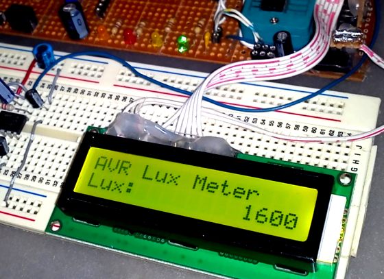
Displaying light intensity in lux
Important note
The purpose of this project was to demonstrate a technique of building a digital lux meter using a simple LDR which was calibrated against a reference photometer. It should be kept in mind that the calibration numbers used in this project are not universal and may not be applied to other LDRs. You have to find out the right numbers for your LDR in the similar way as described here.
This project was written by Shawon Shahryiar from Bangladesh. He works as an Engineer in the Research and Development Cell at ELECTRO Group in Dhaka. If you have any questions or concerns regarding this project, you can contact him at: |
 |
|
|
Why use expensive compiler when all hobby people including Arduino IDE use the free open source avr-gcc compiler.
Your code is useless.
This is cool!
hello,
can anyone tell me whether “TSL257-LF” is able to scan 7 segments digits from lCD dipslay.
Can you help me to build a digital light meter whit LDR,IC555,IClm324,IC7475,IC74192,IC7447,IC74123&five “seven segment”s
Thanks….
I came across your excellent work Shawon. Project description and graphics are above average. We have developed similar device using Arduino Nano processor instead on Atme8L.
Bhaskar Mukherjee
Nice work, but why don’t you use a lookup-table instead of all if & else’s or better, calculate to get the results?
i want to know how to make similar project but by using PIC16F887 microcontroller.. please help.
i want to know that there is op-amp and lcd microcontroller is present another hardware is which hardware is used..
thank you for your usful project.i like to buld green house avr .temp.humidity.light.soil moisture.controller.i hope to get all information for this project .thank you again.regards
I want to make a similar project, but using bpw21 photodiode. I want to know how to calculate the operational amplifier. Thank you very much.
Did you finish the project with bpw21?if yes.can i know about the details
Hi.
I want to buy a LDR sensor u’re using in project.
And I want to know how to calculator op-amp filter ?
Thanks u.
Actually i am trying myself to make programmable LDR switch so this idea would be great 🙂
Can the LDE and the Pot 100K be swapped, that is the pot 100K is connected to 5V and LDR to GND
As @serilas does, I’m also asking myself how the meter works in the UV spectral region.
Do you take into account a light spectral composition? How does the meter work in the UV spectral region?
Pingback: how i can make lux meter in mikroC
software example is not good… this all “elseif” stuff make it big, also, all calibration is hardcoded in firmware. You may keep some calibration tables in eprom and make software “recalibratable”.
Also, output is fixed to some values, and simple change for 1 bit in 535-536 value change output 1600 lx!
The hardware already have some op amps, so “extend” non linear output, so you can simplify your software to integer calculations or even you can use MSB for 8 bit calculations.
Nice project. What LDR value or product ID You use in this project?
Pingback: Another LUX meter using MAX44007 ambient light sensor » Geko Geek
Running Average filter is actually a Digital Low pass filter as discussed in Digital Signal Processing courses.
You can eliminate analog Opamp(s) with software based 16,32 or even 256 point running average low pass filter in your program.
With suitable coefficients chosen you can do it robustly, saving more power for other operations.
By the way Excellent Explanation with nice Hardware.
what a cool project. would you show me digital lux meter project using phototransistor with microcontroller? thank you anyway.
Thanks for the ideas, Im going to calibrate my LDR with a similar tech
very good . thanks
Pingback: Electronics-Lab.com Blog » Blog Archive » Building a digital light meter with a calibrated LDR
Appreciate your effort.
My advice from embedded coding stand point.
The code would be a lot optimized if you change the type of adc_value from float to an integer(fixed point).
Floating point arithmetic is very costly for embedded targets.
RMS value of 512 samples: = sqrt[ (x1^2 + x2^2 + … + x512^2)/512 ]
If sample( or x) is an integer then using a float container for sample (or x) will not give any benifit during the squaring operation.
if you declare samples as integer.. then 512 multiplication options will be simplified from float to int .. code will run much faster .. code density will be better.
Once all samples have been colleted then do a floating point division and take square root
An excellent guest article. Thank you Mr. Shahryiar.
excellent way of explanation with images.