Lab 21: Servo motor control
|
|
A servo motor is a special geared DC motor equipped with an electronic circuit for controlling the direction of rotation, as well as the position, of the motor shaft. Because servo motors allows precise angular positioning of their output shaft, they are used extensively in robotics and radio-controlled cars, airplanes, and boats to control the motion of their various parts. In this lab session, we will first explore what a servo motor consists of and how it works and then illustrate how to interface it with a PIC microcontroller.

Servo motor control using PIC microcontroller
Theory
A servo motor (or servo) is a little box that contains a DC motor, an output shaft (servo arm) which is connected to the motor through a series of gears, and an electronic circuit to control the position of the shaft. The objective of using a servo is to achieve precise angular positioning of an object.
In order to accomplish a servo function, an instantaneous positioning information of the output shaft is fed back to the control circuit using a transducer. A simplest way of doing this is by attaching a potentiometer to the output shaft or somewhere in the gear train. The control electronics compares the feedback signal (which contains the current position of the shaft) from the potentiometer to the control input signal (which contains information of the desired position of the shaft), and any difference between the actual and desired values (known as an error signal) is amplified and used to drive the DC motor in a direction necessary to reduce or eliminate the error. The error is zero when the output shaft gets to the desired position. The functioning block diagram of a typical servomotor is shown below.

Principle of a servomotor

Servo parts (Source: http://tutorial.cytron.com.my/2011/09/19/how-rc-servo-works/)
The control input to a servo is a pulse width modulated (PWM) signal, generally of frequency 50 Hz. This means the pulse should repeat every 20ms. The width of the pulse determines the angular position of the output shaft. An electronic circuit inside the servo converts the PWM signal to a proportional output voltage which is compared with the feedback voltage from the potentiometer. If a difference exists between the two, the control circuit drives the motor in an appropriate direction until the difference becomes zero. A typical value of the pulse width is somewhere in the range of 1.0 to 2.0 milliseconds (ms). For a standard servo, a pulse width between 1.0 ms to 1.5 ms makes the servo to turn clockwise (CW), between 1.5 ms to 2.0 ms makes it to turn counterclockwise (CCW), and a 1.5 ms pulse width turns the servo motor to its center. However, these values could vary depending on the brand and make of the motor. It is advised to read the datasheet of the servo to find the true values of the pulse widths required for positioning the servo at different angles.
Most servos rotate through 180°. However. there are some that could rotate through a full 360° or more. Servos are widely used as the moving joints in robotic arms for their precise angular positioning. They also finds applications in radio controlled (RC) toys. For example, in RC cars they are used in the steering mechanisms, and in RC boats to control the rudder.
A servomotor has three wires: two are designated for power supply (Vcc and Ground) and the third wire is for the control signal.The Vcc wire is usually red and the ground one is either black or brown. The control signal wire comes in white, yellow, or orange color. The servomotor used in this experiment is from iCircuit technologies and has red, brown, and yellow color wires for Vcc, Gnd, and control signal, respectively. It operates at 5.0 V power supply and provides angular rotation through 180°

A typical servo motor
The pulse width values for different angular positions of this servo are provided in the table below. Remember that the repetition rate of the pulse should be 50 Hz (period of 20 ms).

Servo timing information for different anglular positions

Different angular positions of the servo arm
Circuit
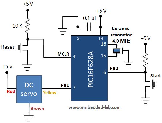
The circuit diagram of this experiment is depicted below. The control input for the servo is derived from the RB1 pin of the PIC16F628A microcontroller that operates at 4.0 MHz using an external ceramic resonator. A tact switch is connected to the RB0 pin to provide user input to control the position of the servo arm. The operation part of this experiment is described in the software section below.

Circuit diagram for servo motor control demonstration

Circuit setup on breadboard
Software
The firmware for PIC16F628A is written in MikroC Pro for PIC compiler. The Timer0 module is operated as timer with prescaler 1:256 to generate an approximate 20 ms gap between the two successive PWM pulses. Keep in mind that the clock frequency is 4.0 MHz, which results into 1 ?s machine cycle, thus simplifying the math involved in calculating the delay using Timer0. MikroC provides a built-in library function, Delay_Cyc(), that generates a variable clock cycles delay. This function is used to vary the width of the control pulse from 0.7 to 2.3 ms. When the circuit is first powered up or reset, a 50 Hz PWM signal with 0.7 ms pulse width is continuously generated at RB1 pin. This control signal moves the servo arm clockwise all the way to the end, which is considered as 0 angular position. When the tact switch connected to the RB0 pin is pressed, the width of the pulse is increased by 0.2 ms, which turns the shaft counterclockwise (CCW) by approximately 22.5°. So each time the switch is pressed, the pulse width is increased by 0.2 ms, and the shaft further rotates in CCW direction. After 8 successive presses of the switch, the pulse width becomes 2.3 ms and the shaft reaches the other end (180° angular position). On 9th press, the pulse width is reset to 0.7 ms, and the motor shaft rotates in clockwise direction until it gets at 0 angular position back. In the program, the variable ‘i’ stores the pulse width information (pulse width = i*10*10 microseconds) and is varied from 7 to 23 in a step of 2. When i=7, pulse width is 7*10*10 = 700 microseconds (0.7 ms), and when i=23, the width is 2.3 ms.
/* Lab 21: Servo motor Control using PIC16F628A MCU: PIC16F628A running at 4.0 MHz, MCLR enabled, WDT is OFF, Brown Out Detect disabled Written by: Rajendra Bhatt (www.embedded-lab.com) 2012/03/29 Description: User input switch is connected to RB0 and Servo Control signal is generated from RB1 pin. */ sbit SW1 at RB0_bit; sbit Control at RB1_bit; unsigned short i=7, delay; void interrupt() { delay = i*10; Control = 1; Delay_Cyc(delay); // Generates delay equal to 10*delay clock cycles Control = 0; TMR0 = 180; // TMR0 returns to its initial value INTCON.T0IF = 0; // Bit T0IF is cleared so that the interrupt could reoccur } void main() { CMCON = 0x07; // Disable Comparators TRISB = 0b00000001; PORTB = 0; OPTION_REG = 0x07; // Prescaler (1:256) is assigned to the timer TMR0 TMR0 = 180; // Timer T0 counts from 180 to 255 to create ~20 ms period INTCON = 0xA0; // Enable interrupt TMR0 and Global Interrupts do{ if(!SW1){ // Change pulse width when Switch is pressed Delay_ms(300); i = i+2; if(i>23) i=7; } }while(1); } |
Download complete source and HEX files
Output
After loading the HEX file into the PIC16F628A microcontroller, you can watch the servo controller in action. Watch the demo video at the bottom to see the output of this experiment.

Servo control
|
|
Pingback: Servo Motor Controller Tutorial | oldmanhealth.com
Could you post similar porjects doing same as this ?
I want to know how to control servo angle according to Analog inputs
(P.S…. 1 ?s is mistyped.)
Hi
I was wondering why can you use the 4MHz internal oscillator of the Pic microcontroller?
also can the project be done on a 8 pin Pic microcontroller instead of 18pin which you have used?
Thanks for all the help in advance.
hi sir..nice work u did there..
im using pic18f45k22, and i have changed the code , but its not working..could u help me?
Awesome work my friend 🙂
hi there, i just wanted to ask how to control the servo to move from position 0 degrees to 90 degrees in 10s?
thanks
hi friend! i am really impress with your work .
it would be nice if u could answer some of my questions?
1,How do we control the speed of the servo motor & how do we take care of the forward and reverse motion?
in the blog it is written : if (i>23) i = 7 ?
I have added extra sentences in the software section to describe the role of i.
HI Raj
What does it mean?
if(i>23) i=7;
thanks!
marC:)
The tutorial was quite help full….
What is the use of a servo motor?
thank you!
marC:)
hi! i am really impress with your work (:
it would be nice if u could answer some of my questions?
1) is this code workable for PIC18F4620? any changes needed?
2) can u send me the code including header, #define and etc for reference?
i am a beginner for embedded programming, so pls help me to understand?
thank you!!
How do we control the speed of the servo motor & how do we take care of the forward and reverse motion? Pls reply me. Thanks.
Pingback: Controlando un servo con pic « SparkJunkies
Ok, so how do you vary the speed, stop, continue and/or reverse the direction smoothly? I haven’t found any explanation or demontration of this. I’m stuck with the problem of making a variable zoom control for a vari-focal lens. Any suggestions?
Pingback: Control de un Servo Motor_Bairesrobotics | Bairesrobotics
Pingback: Control de servo motores con un microcontrolador | Automatismos Mar del Plata