chipKIT Tutorial 2: Serial communication with PC
|
|
The PIC32 processor on the chipKIT Uno32 board provides two hardware serial ports. One of these is used by the on-board FTDI chip to create an USB-UART interface that allows the MPIDE tool running on the PC to communicate with the Uno32 board through an USB port. In this tutorial, we will use the same USB-UART interface to demonstrate a two-way asynchronous serial communication between the Uno32 and the PC. The Uno32 board receives a serial command through the PC’s USB port to turn an external LED on and off. In return, the Uno32 board acknowledges to the PC by sending the new state of the LED.
Controlling an external LED with serial command from PC
Theory
The chipKIT Uno32 board features two hardware serial ports: UART port1 and UART port2. Pin 0 and Pin 1 serves as RX and TX for UART port1. These pins are also used by the FT232R USB-to-Serial converter on the board. Similarly, UART port2 uses Pin 39 and Pin 40 for RX and TX functions, respectively. We will use UART port1 in this tutorial as it allows serial communication with the PC over an USB port.
The MPIDE has got a built-in serial monitor tool that allows you to watch any data that the Uno32 sends out its serial port. It also let you send characters from the PC back to the Uno32 board over the same serial interface. You can open the serial monitor window by clicking on the serial monitor button in the toolbar. In a Windows version of MPIDE, the serial monitor window looks like this.

MPIDE serial monitor window
There is a blank text box at the top where you enter text that you want to send to the chipKIT Uno32 board. Below that is a white space where the serial data sent by the Uno32 board will be displayed. On the bottom right side, you can select the Baud Rate (speed) of the serial communication. The default setting for Baud Rate is 9600 baud but you can select other baud rates from the drop-down menu. Note that the chipKIT board must be configured to the same baud rate for serial communication. You must free up the serial port before returning back to the programming mode of MPIDE. You can do that by closing the serial monitor window.
Circuit setup
The experimental circuit setup for this tutorial is very simple. All you need is an LED and a 220? series resistor. The LED will be controlled from a serial command received from the PC. The picture below shows the LED connections to the Uno32 board. The LED is connected to Pin 2. Note that during serial communication, digital pins 0 (RX) and 1 (TX) are occupied and cannot be used for other I/O purposes. The board is connected to an USB port and receives power from there.

An external LED controlled through serial commands from a PC
Writing sketch
In your setup function, you need to tell the Uno32 to open serial port. This is done by Serial.begin() command. The number within the parenthesis sets the baud rate of the serial communication. The typical baud rate for communicating with the computer is 9600 but other speeds are also supported. Next you need to define Pin 2 as output, which can be done using pinMode() function.
In order to send data from Uno32 to PC, MPIDE mainly offers two commands: Serial.print() and Serial.println(). Both of them send whatever is inside the parenthesis to the PC through the serial port. On PC’s side, the received data is displayed on the serial monitor window. However, the difference between using print and println is the way they print the data out the serial port. When you use Serial.print(), then the cursor remains at the end of whatever you just printed. So, if there is another print command following that then the new data will show up in the serial monitor window at the end of the previously received data, along the same line. On the other hand, Serial.println() prints data with a linefeed at the end that drops the cursor down to the next line after the data has been printed. Both of these commands can take many forms, which are described very well in the Arduino serial library page.
Here’s the complete program to control the external LED with a command byte sent from the PC over the serial line. If the Uno32 receives ‘1’ from the PC, it turns the LED on. If it receives ‘0’, the LED is turned off. In response to the command, the Uno32 prints the new status of the LED back to the PC.
/* Tutorial 2: Serial interface between PC and chipKIT Description: chipKIT UNO32 receives commands from a PC through serial port and control an external LED connected to pin 2 Board: chipKIT UNO32 */ const int LED_PIN = 2; // LED is connected to digital I/O pin 2 int SERIAL_DATA; // Variable to store incoming serial byte void setup() { Serial.begin(9600); // Sets the baud rate for serial transmission pinMode(LED_PIN, OUTPUT); // Send these messages to PC only once Serial.println("Serial interface between PC and chipKIT"); Serial.println("1: LED ON, 0: LED OFF"); digitalWrite(LED_PIN, LOW); // LED is off initially } void loop() { if(Serial.available()>0){ // Check if serial data is available. SERIAL_DATA = Serial.read(); // If yes, read the incoming byte if(SERIAL_DATA == '1') { // Check if the received byte is '1' digitalWrite(LED_PIN, HIGH); // If so, turn the LED ON Serial.println("LED is ON"); // and acknowledge. } if(SERIAL_DATA == '0') { // If the received byte is '0', digitalWrite(LED_PIN, LOW); // turn the LED OFF and Serial.println("LED is OFF"); // acknowledge. } } } |
The Serial.begin(9600) opens the serial port of Uno32 and sets the baud rate of 9600. You can see there are two Serial.println() commands inside the setup function. They print two text messages over the serial line, which are displayed on the serial monitor. Since setup function is executed only once, these messages are also printed only once at the beginning. Inside the loop function is used the Serial.available() command, which checks to see if any characters have been sent down the serial port by the PC. It returns the number of characters available for reading from the serial port. Once there’s data available, it can be read using Serial.read() command. The Uno32 then compares the received byte with ‘1’ and ‘0’ to take proper action with the LED.
Output
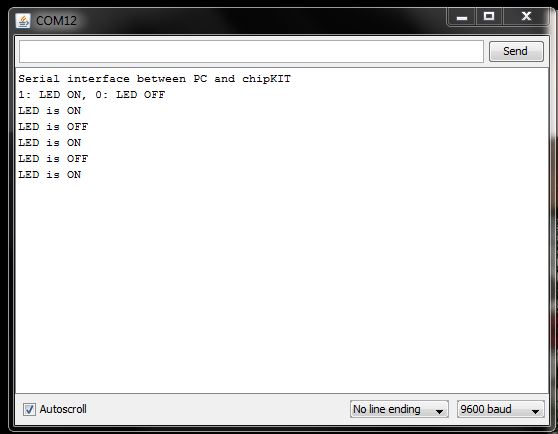
Verify and upload the above sketch into the Uno32 board. Open the serial monitor window and make sure it is configured to use a baud rate of 9600. Reset the Uno32 board and wait until it gets out of the bootloader mode so that it could execute the user program. You will read two text lines (“Serial interface between PC and chipKIT” and “1: LED ON, 0: LED OFF“) on the serial monitor that were printed by the Uno32. If you type in ‘1’ in the send box at the top and click on send button, it will be sent over the serial line. The Uno32, on receiving the command byte, will turn the LED on. If a ‘0’ is sent, the LED will be turned off. The Uno32 board acknowledges to the receieved command by printing back the new state of LED on the serial monitor. If the received character is other than ‘0’ and ‘1’, then it will be ignored by Uno32.

Controlling LED through serial command
LED is turned on and off through a command received from PC over serial interface
|
|