Netduino Day 1: Basic Input and Output
|
|
We will start our Netduino tutorial series with a very basic project of flashing an LED. The objective of this project is to explore basics of Netduino I/O pins as well as to make sure that everything is setup correctly, including software installation and hardware setup. In this project, we will use an Analog pin to read a potentiometer’s analog output, and a digital pin to flash an LED. The frequency of LED blinking is varied based on the potentiometer output. It will blink at an interval of 10 milliseconds to 1000 milliseconds based on the wiper position of the potentiometer. In Netduino, you can set the range for 10-bit ADC output of an analog port.Writing code will be carried out in Visual Studio with C# as programming language.

Netduino based Flashing LED
If you are not sure where to write a code or how to connect your Netduino (or Netduino Plus) to your computer then please go through Getting Ready for Netduino / Netduino Plus Tutorials
Circuit Setup and Theory

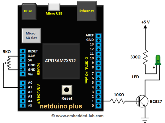
Flashing LED with Potentiometer Circuit Diagram
We can split the experiment into two parts, first around analog input, which is around the potentiometer and second around the digital I/O i.e. around transistor and LED. In the analog section, we simply connected two end-leads of potentiometer to the ground and 3v3 and the middle lead to the A1 port of the Netduino. In our code, we have defined the range of this analog device from 10 milliseconds to 1000 millisecond. So, when the pot is rotated (its resistance is changed) , microcontroller will feed us a value between given range accordingly. Guess what? We converted our analog signal to digital signal! Potentiometer is an analog device and we ranged it’s value from 10 milliseconds to 1 second.
In the second half of the connection, the D1 (Digital I/O) of Netduino is connected to the base of a transistor along with a resistor. This transistor is used as a switch in the circuit. When we set the D1 port to high, transistor will reach its saturation state and hence current starts flowing along Base and Collector. The moment this happens, our LED will turn ON, because a complete circuit is formed from 5v to the ground. Accordingly, when D1 port is low, no current will flow through the Base and Collector causing an incomplete circuit from 5v to the ground. Hence LED will turn Off.
Connection With Netduino / Netduino Plus

Connection with Netduino: Flashing LED with Potentiometer
C#.NET Program
As we can see the program is really simple. The first few lines created an AnalogInput instance and set its range from 10 to 1000. Then another instance of OutPort has been created to send the signal to an LED. Then we have a very simple infinite loop which will turn the LED to on and off. The delay value is coming from the Analog Input which is a potentiometer in our case. If the analog value is 50 then the LED will turn on for 50 milliseconds and then stay off for the same amount of time.
// use any analog pin AnalogInput aInPin = new AnalogInput(Pins.GPIO_PIN_A1); // give a range. aInPin.SetRange(10, 1000); // at D1, we will send signal for LED OutputPort led = new OutputPort(Pins.GPIO_PIN_D1, false); while (true) { // Read Pot value int potValue = (int)aInPin.Read(); Debug.Print("Pot Value: " + potValue.ToString()); // turn LED ON led.Write(true); // let it be ON for potValue Thread.Sleep(potValue); // turn LED OFF and let it stay OFF for potValue led.Write(false); Thread.Sleep(potValue); } |
Outputs
You will see the LED will blink and its blinking rate is dependent on potentiometer (pot) value. If you turn the pot all the way to one end, it will stay ON for a second and OFF for a second. Similarly, if you turn the pot all the way to the other side, LED will appear flickering because it’s only staying ON for 10th of a second. A short Video…
Downloads
1) C#.NET code (A complete solution file)
What Next
In our next tutorial, we will learn about LCD (Liquit Crystal Display) and display the information that we want in the LCD. In this next tutorial, we will learn several options to send command or display the information in the LCD. Interfacing a Character LCD with Netduino Plus
|
|
Good Tutorial.
Pingback: Curso básico de Netduino Plus Parte 1 « Soloelectronicos
Why the need for a transistor. Can’t a 5v netduino ouptut simply go through a current limiting resistor to ground? I’ve done this lots on Arduino, not sure if I’m missing something
Regards
Mark
Oh and the video is not working for me (says it’s private)
As I’m making my first steps with the Netduino in VB instead of C#, I’ve adapted the code for VB. Hope it helps other people.
In my case I have connected the LED directly to D13 and GND so I have left out the whole second half of the connection with the transistor etc.
Imports Microsoft.SPOT

Imports Microsoft.SPOT.Hardware

Imports SecretLabs.NETMF.Hardware

Imports SecretLabs.NETMF.Hardware.Netduino
Module Module1
Sub Main()
'use any analog pin
Dim aInPin As New AnalogInput(AnalogChannels.ANALOG_PIN_A1)
'set offset to 10 and range to 990 for a total range of 10 to 1000
aInPin.Offset = 10
aInPin.Scale = 990
'use pin D13 for LED signal
Dim led As New OutputPort(Pins.GPIO_PIN_D13, False)
While (True)
'Read Pot value
Dim potValue As Integer = CInt(aInPin.Read())
Debug.Print("Pot value: " & potValue.ToString())
'turn LED ON
led.Write(True)
'let it be ON for potValue
Thread.Sleep(potValue)
'turn LED OFF and let it stay OFF for potValue
led.Write(False)
Thread.Sleep(potValue)
End While
End Sub
End Module
Hi. I’m a beginner. This isn’t working for me. When I type in the code defining the AnalogInput pin, it gives me these errors:
1. Cannot convert from ‘Microsoft.SPOT.Hardware.Cpu.Pin’ to ‘Microsoft.SPOT.Hardware.Cpu.AnalogChannel’
2. The best overloaded method match for ‘Microsoft.SPOT.Hardware.AnalogInput.AnalogInput(Microsoft.SPOT.Hardware.Cpu.AnalogChannel)’ has some invalid arguments
Any help would be appreciated.
Techie Dude, I had the same errors. Found the solution on the Netduino Forums.
Add a reference to SecretLabs.NETMF.Hardware.AnalogInput
Then change the line of code to:
AnalogInput aInPin = new SecretLabs.NETMF.Hardware.AnalogInput(Pins.GPIO_PIN_A1);
Should be good to go!
I hope this helps.
Tim