Tag Archives: LED


RF detection using a common LED

Hardware hacker b.kainka has posted on Hackaday.io a very interesting trick of detecting a RF signal using an everyday LED and ATtiny13 microcontroller (other microcontrollers should work too).

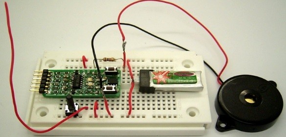
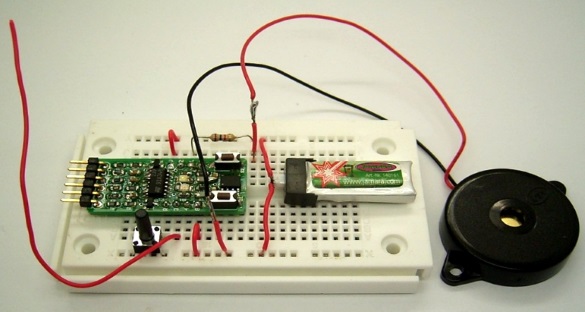
I am using the ATtiny13 on the Sparrow board. https://hackaday.io/project/4926-cheepit-sparrow-dev-boards-for-smartphones LED2 is connected to port B.3 which is ADC(3) as well. So why not connect an Antenna here. The LED should work as a detector diode. A bias voltage is needed. So I should switch on the internal pullup.

Now it works fine! Don’t believe it? Watch the video. To get it sensitive enough I had to use one more trick. I switch on the pullup for a very short time. This will charge the LED which is also a little capacitor of only a few picofarads. Voltage may rise up to 2 V. Then I switch back to high Z. The LED is discharged down to about 1.5 V after some microseconds. But in the presence of an RF signal it will discharge a little lower. Several RF pulses may result in an integrated loss of LED voltage. That’s why I call it an integrating RF detector. In the end I need something like 50 mV at 100 kHz to get a clear result.

RF detection using a common LED

RF detection using a common LED

Netduino Day 1: Basic Input and Output

We will start our Netduino tutorial series with a very basic project of flashing an LED. The objective of this project is to explore basics of Netduino I/O pins as well as to make sure that everything is setup correctly, including software installation and hardware setup. In this project, we will use an Analog pin to read a potentiometer’s analog output, and a digital pin to flash an LED. The frequency of LED blinking is varied based on the potentiometer output. It will blink at an interval of 10 milliseconds to 1000 milliseconds based on the wiper position of the potentiometer. In Netduino, you can set the range for 10-bit ADC output of an analog port.Writing code will be carried out in Visual Studio with C# as programming language.

Netduino based Flashing LED

Read more

Lab 1: Flashing an LED

Description

Today is our first session in PIC microcontroller lab, and we will begin with an experiment that flashes an LED on and off. While this looks very simple it is the best project to start because this makes sure that we successfully wrote the program, compiled it, loaded inside the PIC, and the circuit is correctly built on the breadboard.

In this lab session we will connect an LED to one of the port pin of PIC16F688 and flash it continuously with 1 sec duration.

Required Theory

You must be  familiarized with,

  • digital I/O ports (PORTA and PORTC) of PIC16F688
  • direction control registers, TRISA and TRISC
  • special function registers CMCON0 and ANSEL

If you are not then please read this first: Digital I/O Ports in PIC16F688.

Circuit Diagram

To our basic setup on the breadboard (read Getting Ready for the First Lab), we will add a light-emitting-diode (LED) to port pin RC0 (10) with a current limiting resistor (470 Ohm) in series. The complete circuit diagram is shown below.

Read more

PIC based shaking LED dice

Electronics dice projects using push buttons are available all over the internet. This one is a little bit different. It is meant to provide the real feeling of shaking a dice by using a spring with weight and a wire. The two make and break contacts when shaken. The PIC16F688 microcontroller detects the contacts between the spring and the wire, and rolls the dice. After the spring motion stopped completely, the dice output number is displayed with glowing LEDs.

Read more