STM32 Serial Communication
|
|
STM32 micros just like any other micro provide hardware for serial communication. As we all know serial communication is a very important tool for debugging, connecting with external hardware like RFID, GPS, GSM modems, etc. and for performing other communication-related tasks. STM32s have several hardware serial (USART) ports. The number of ports available in a STM32 micro is dependent on device family type and the device itself. Typically there are at least 5 serial ports. Apart from the basic serial communication needs, STM32’s USART hardware also have support for LIN, one-wire, smart card protocols, SPI and IrDA. We can even utilize STM32’s DMA controller with USART hardware to achieve high speed automated data communication. Thus these hardware are truly universal synchronous-asynchronous receiver-transmitters.
In any standard serial communication, we need three wires – TX, RX and GND. TX pin is an output pin and transmits data serially to another device’s RX pin. RX pin is an input pin and is responsible for receiving data from another device’s TX pin. The two devices connected in this way must have same ground (GND). There are other pins like CTS and RTS which are used for hardware flow control. Additionally there’s also another pin called CK. It is transmitter’s clock output and used usually in SPI and other modes.
Depending on package, USART pins are arranged in the following pattern:
| BGA100 | LQFP100 | LQFP48 | LQFP64 | Pin Name | USART/UART |
| D9 | 67 | 29 | 41 | PA8 | USART1_CK |
| C10 | 70 | 32 | 44 | PA11 | USART1_CTS |
| B10 | 71 | 33 | 45 | PA12 | USART1_RTS |
| C9 | 68 | 30 | 42 | PA9 | USART1_TX |
| D10 | 69 | 31 | 43 | PA10 | USART1_RX |
| G3 | 29 | 14 | 20 | PA4 | USART2_CK |
| G2 | 23 | 10 | 14 | PA0 | USART2_CTS |
| H2 | 24 | 11 | 15 | PA1 | USART2_RTS |
| J2 | 25 | 12 | 16 | PA2 | USART2_TX |
| K2 | 26 | 13 | 17 | PA3 | USART2_RX |
| K8 | 51 | 25 | 33 | PB12 | USART3_CK |
| J8 | 52 | 26 | 34 | PB13 | USART3_CTS |
| H8 | 53 | 27 | 35 | PB14 | USART3_RTS |
| J7 | 47 | 21 | 29 | PB10 | USART3_TX |
| K7 | 48 | 22 | 30 | PB11 | USART3_RX |
| B8 | 79 | – | 52 | PC11 | UART4_RX |
| B9 | 78 | – | 51 | PC10 | UART4_TX |
| B7 | 83 | 54 | PD2 | UART5_RX | |
| C8 | 80 | – | 53 | PC12 | UART5_TX |
Personally I’m interested in LQFP packages, particularly 48 and 64 packages as they are mostly used in the most common STM32 development boards. I suggest locating USART/UART pins before working with them.
Things to keep in mind
- Only USART1 can operate with clocks up to 72 MHz while the rest can operate at 36 MHz maximum. This is because USART1 can get full system clock while the others get half of that.
- USART1 is connected to the high speed APB2 bus while rest are connected to the lower speed APB1 bus. Most communication peripherals are connected with APB1 bus.
- GPIO pins associated with USART hardware must be set as alternate function I/Os and it should be enabled before the hardware modules’ use.
- TX pins should be set as low speed (2 MHz) AFIO push-pull outputs while RX pins should be set as floating inputs. RX pins can also be set as inputs with pull-ups or pull-downs if needed.
- If flow control is not used then the associated flow control pins can be left as GPIO pins. For instance PA8, PA11 and PA12 of USART1 can be used as GPIO pins if flow control is not needed.
- USART/UART pins can be remapped using AFIO_MAPR register. By default, the default pins like PA9 and PA10 for USART1 are used and not remapped elsewhere because this register is by default cleared and hardware remapping is not enabled.
- In exception conditions, APB1RSTR and APB2RSTR registers can be used reset USART/UART hardware.
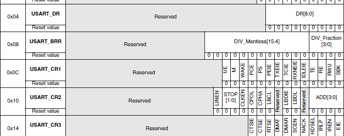
This is USART register map:
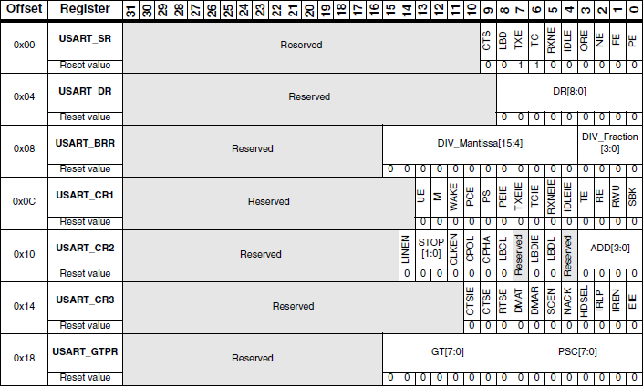
For better view check STM32F10x Reference Manual’s (RM) page 799. These registers are all that are related to USART/UART hardware. Although the registers are 32 bit wide, the upper nibbles are left unused and so they should be written 0s. This is done by hardware too.
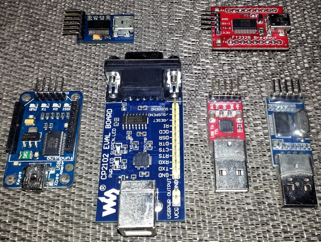
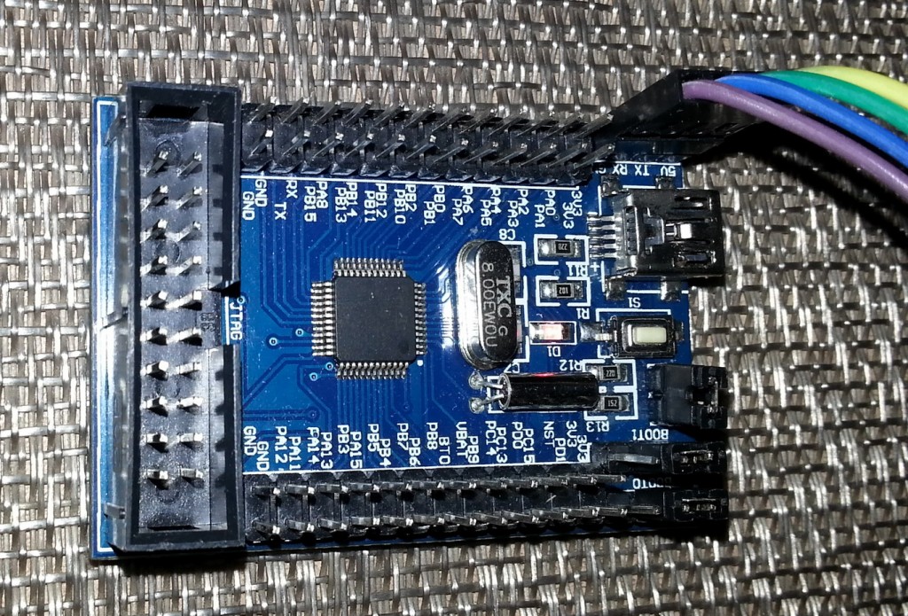
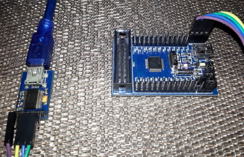
It should also be noted that STM32s operate at 3.3V and so avoid using 5V devices directly. Although some STM32 pins are 5V tolerant I would suggest avoiding 5V device interfacing. I will recommend using popular MAX232-based circuit for interfacing with RS232-level ports or USB-TTL converters like FT232, CP2102, PL2303, etc. for connecting with PCs and laptops. I’m using a FT232R breakout board here.
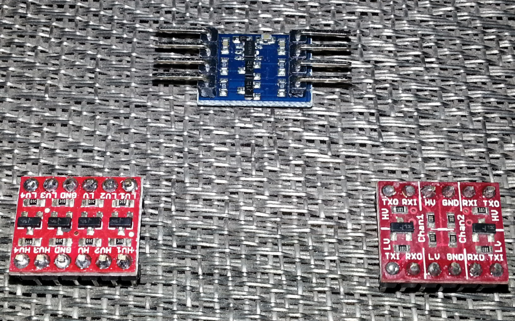
If needed a logic level converter may also be used.
Baud Rate Calculation
In most 8 bit micros when calculating baud rates for serial communication, baud rates are usually programmed to the nearest integer values, ignoring the fractional portions. This is completely the opposite in STM32s. One can also program the rounded fractional values too. It is not a complex process in any way. In any floating point number there are two parts – an integer part (before decimal) and a fractional part (after decimal). STM32’s RM calls these parts in a mathematical literature as DIV_Mantissa and DIV_fraction.
USART_BRR Register is responsible for keeping baud rate-related values.
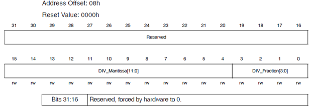
As can be seen the lower four nibbles store the fractional part of baud calculation while the upper bits till reserved locations keep the integer part. The reserved portion should always be cleared (set as 0s).
According to RM:
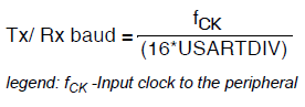
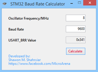
For instance, suppose fCK is set to 8MHz and the baud rate for serial communication is set to 9600. In this case USART_BRR should be:
USART_BRR = 8,000,000 / (9,600 x 16) = 52.083.
Thus the mantissa will be 52 or 0x34 and the fractional part will be (16 x 0.083) = 1.3 approximately, after rounding it becomes 1 or 0x01;
Now in the code we’ll have to shift the mantissa part four times or multiply by 16 as the mantissa starts from 4th position of USART_BRR register and then add 1 (fractional part) with it. Thus the USART_BRR will be loaded with (52 x + 1) = 833 or 0x341. We’ll be setting USART1 with this baud rate value in our code.
The Other Stuffs
Fortunately right after reset all USART/UART registers have favorable default values as such that there’s no parity and one stop bit. This is what we usually use. The USART_DR register is buffer that is responsible for data transmission and reception. Data to be sent to another device is written here while data to be received is also buffered here. However we need to know if there’s a transmission or reception going one. To know this we can either use interrupt methods or read USART status register, USART_SR flags.
The Software Part
Setting up registers for USART is very easy. Just as always we need to enable the required I/O peripherals and hardware. Since we are dealing with USART1 only and it is connected with APB2 bus, we will have to set RCC_APB2ENRbits.USART1EN bit. We’ll also need to enable GPIOA pins as USART1, by default, uses PA9 and PA10 pins. We’ll have to set PA9 and PA10 in AFIO mode too as I already stated. Before enabling the USART hardware completely we should first set the baud rate value for BRR register. This is followed by setting the USART hardware and its TX and RX options.
void setup()
{
RCC_APB2ENRbits.IOPAEN = 1; //Enable GPIOA
RCC_APB2ENRbits.USART1EN = 1; //Enable USART1
GPIOA_CRH = 0x4A0; //Set PA9 and PA10 as AFIO pins
USART1_BRR = 0x341; //Set value for required baud rate
USART1_CR1bits.UE = 1; //Set USART1
USART1_CR1bits.RE = 1; //Set USART1 RX to receive incoming data
USART1_CR1bits.TE = 1; //Set USART1 TX to send data
}
Transmitting and receiving data needs only a few lines of code.
unsigned char USART1_receive()
{
while(USART1_SRbits.RXNE == 0); //wait until data is available for reading
return (0xFF & USART1_DR); //return read data
}
void USART1_send(unsigned char value)
{
USART1_DR = value; //transfer data to DR register
while(USART1_SRbits.TXE == 0); //wait until data transmission is complete
}
As stated earlier, the DR (Data Register) register actually deals with incoming and outgoing data. It is like a temporary data buffer. The code example above is self-explanatory. We wait until data is received or transmitted successfully. This is done by monitoring SR (Status Register) hardware flags set by the hardware peripherals responsible. Thus the above code is based on polling method. I have also included examples with interrupt and MikroC’s built-in library in the compressed folder and I leave them for readers to explore should they understand my explanation.
Last Few Words
One more thing to note – MikroC’s libraries are good and easy to use but they are resource expensive and have limited functionalities. For instance the serial communication codes without MikroC’s library assistance took only about 1% of STM32F103C8’s space, i.e. 1% of 64kB = 0.64kb or 640 bytes while with USART library this figure becomes 5% of 64kB or 3.2kB. ARM chips typically have large memory resources and so using library for fast development or testing is not a big deal. It’s up to the coder to decide what to do. Personally I use library functions for rapid prototyping and testing. I also use them in professional works when their usage doesn’t cause any problem. I only go down to every bits-and-bytes when desperately needed.
I have also made a USART_BRR calculator software which will calculate the BRR register value for a given clock frequency and required baud rate. It’ll greatly relieve from tiresome calculations.
Demo
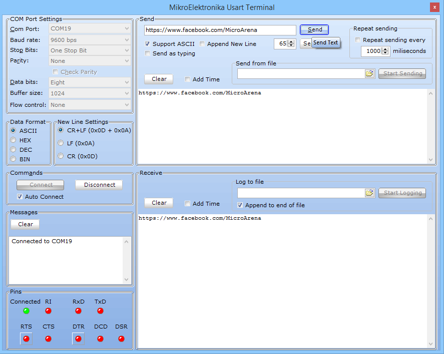
All of the code examples are just USART loops and so whatever we write to STM32 is returned to PC USART terminal program. MikroC like many other IDEs have USART terminal support and we can use it very easily. Usually the USART1 hardware is also the hardware we use for bootloader mode and provided that the usual USART pins are not remapped elsewhere, we can use it for USART code checks without wiring extra stuffs. We wire it for uploading codes before tests. This is what I did in my examples.
Video Link: https://www.youtube.com/watch?v=vjzGVh5HHhQ
Download link for the GUI and the demo codes: STM32 USART.
Last but not least I will suggest readers going through the STM32F10x Reference Manual’s USART section. It’ll surely help building vital concepts.
Happy playing with STM32.
Repository: https://github.com/sshahryiar/STM32-Tutorials
Author: Shawon M. Shahryiar
https://www.youtube.com/c/sshahryiar
|
|
Great posting thanks!
Welcome…. 🙂