Microcontrollers usually don’t have specific ports for measuring currents, but they do have ADC channels through which you can measure analog voltages of a certain range. This means a dc current can be indirectly measured by a microcontroller’s ADC channel by first converting the current into voltage. The simplest way of doing this is to place a resistance in series with the current path and measure the voltage drop across it. But hold on, if you place an additional resistance in the circuit, it will affect the original current. Therefore, we need to use a very small value resistance so that it’s effect in the circuit current won’t be significant.
Resistors with values less than 1 ? are available in electronics stores. Depending upon the amount of current in the circuit, you need to choose proper power rating for the resistor. Suppose, if you pick 0.47 ?, and the maximum current in the circuit is about 2 A, then the resistor should have the capacity of dissipating 4 x 0.47 ? 2 Watts of heat.
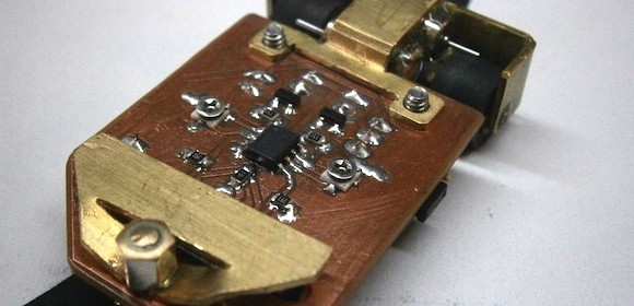
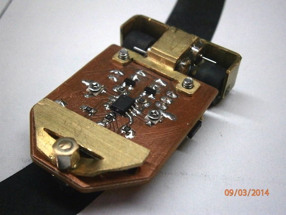
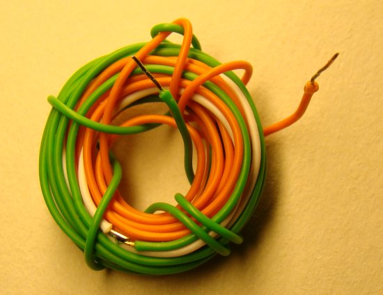
You can also make a small value resistance by yourself. Yes, by simply winding a copper wire into coil. I have made one from a 5 ft long solid copper wire (22 AWG) with plastic insulation on outer side, as shown below.

Current sensing resistance
Now lets measure its resistance. The resistance can be measured directly with a digital multimeter. My digital meter shows its value equal to 0.3 ?. This measurement may have higher uncertainty as it is very small and most multimeter does not show values beyond 1 decimal digit. The resistance can also be measured using Ohm’s law. Connect a 47? ? resistor in series with the coil resistance (Rs) and supply a 5V power as shown below. Next, measure the voltage across Rs and current through it separately using the multimeter. In my case, I found the measured voltage and current values to be 24.1 mV and 84.3 mA, respectively. This gives the resistance of the coil is about 0.286 ?.

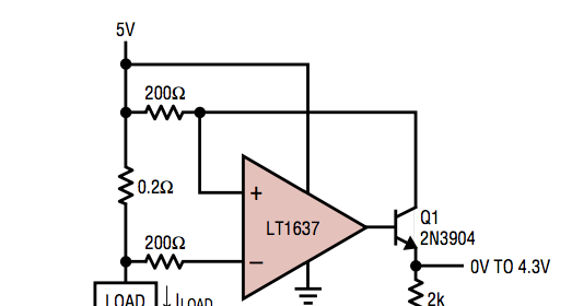
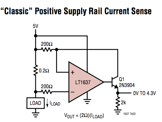
Now, suppose that the range of current to be measured using this coil resistance is from 0-2 A. Then the voltage drop across the coil resistance will be somewhere from 0 – 0.57 V. Because of its low dynamic range, this voltage signal may not be accurately measured with a microcontroller’s ADC module. So this requires some sort of voltage scaling. One way to achieve that is by using an operational amplifier circuit as shown below.

Opamp as a voltage scaler
In the circuit, Rs is the low value current sensing resistor (our coil resistor) which is connected in series with the load resistor. Our objective is to derive the load current (I). The low voltage drop across Rs is amplified by the non-inverting amplifier. The gain of the amplifier is set by Rf and Ri resistors. For Rf = 10 K, and Ri = 1.3 K, the gain of the amplifier would be about 8.7. This is enough to linearly scale Vs (0-0.57 V) to Vo (0- ?5 V). Now you have 0-5 V voltage signal that corresponds to 0-2 A current through Rs. This voltage signal is now more appropriate for ADC conversion with Vref = 5 V.
Vo = 8.7 x I x Rs = 2.49I (Rs = 0.286 ?)
=> I = Vo/2.49.
For 10-bit ADC with Vref = 5 V, resolution = 5/1024 = 0.0049 V. For input signal Vo, the ADC O/P will be Vo x 0.0049. Thus,
I = ADC O/P x 0.0049/2.49 = 0.00197 x ADC O/P
The current resolution would be therefore 0.00197 A (? 2 mA).