Dual 4-digit seven segment LED display with SPI interface
|
|
This project is an extension of my previous MAX7219 based SPI seven segment LED display module. The new display features eight 7-segment displays arranged in two rows of four digits. The on-board MAX7219 driver enables you to easily add eight 7-segment LED displays to your project using only 3 I/O pins of microcontroller. The major advantage of using this board is the time-division multiplexing operations required for continuous refreshing of the display digits are performed by the MAX7219 chip, thereby keeping the microcontroller free for doing other pressing tasks. It is suitable for displaying two variable values simultaneously in a project, such as displaying temperature and humidity, or current and voltage, etc.

8-digit seven segment LED display with serial interface
Key Features:
- based on MAX7219 display driver
- SPI interface (3 pins)
- operates at +5V supply
- individual control of all digits and decimal points
- display brightness control through software
- dimensions 1.95? x 1.95? (50mm x 50mm)
- two 0.36? 4-digit seven segment LED display
The circuit diagram of this project is very simple (shown below) and derived from the datasheet of the MAX7219.

Circuit diagram as described in the datasheet of MAX7219

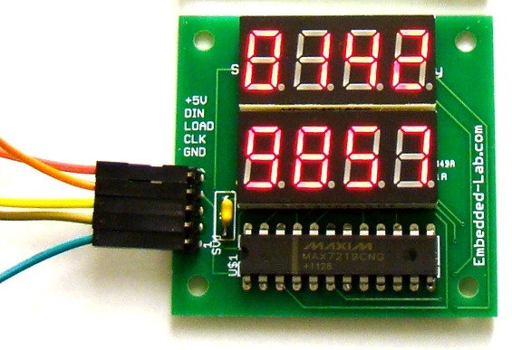
Assembled display board
In the above board, digits from right to left in the first row are DIG0 through DIG3, whereas in the second row, the digits from right to left are DIG4-DIG7. The following example code is written in C and compiled with mikroC Pro for PIC compiler to illustrate how to interface this display module with the PIC12F project board. The program is for a dual 4-digit decimal counter. The first row of the display will be an up counter counting from 0000 to 9999 with one second duration. Meanwhile, the second row will count in reverse order from 9999 to 0000. The microcontroller used in the PIC12F board is PIC12F683. The details of MAX7219 registers and their initialization is described in my previous article Serial 4-digit seven segment display module.
/* Project: 4-digit Up/Down counter using SPI 7-segment LED display MCU: PIC12F683 running at 4.0MHz internal clock, MCLR disabled Date: June 26, 2012 */ // Define Soft-SPI connections #define CS_Pin GP0_bit #define MOSI_Pin GP1_bit #define CLK_Pin GP2_bit void SPI_Write_Byte(unsigned short num){ unsigned short t, Mask, Flag; CLK_Pin = 0; Mask = 128; for (t=0; t<8; t++){ Flag = num & Mask; if(Flag == 0) MOSI_Pin = 0; else MOSI_Pin = 1; CLK_Pin = 1; CLK_Pin = 0; Mask = Mask >> 1; } } void MAX7219_INIT() { // Disable Shutdown mode CS_Pin = 0; // CS pin is pulled LOW SPI_Write_Byte(0x0C); // Select Shutdown register SPI_Write_Byte(0x01); // Set D0 bit to return to normal operation CS_Pin = 1; // CS pin is pulled HIGH // Set BCD decode mode for digits DIG0-DIG3 CS_Pin = 0; // CS pin is pulled LOW SPI_Write_Byte(0x09); // Select Decode Mode register SPI_Write_Byte(0xFF); // Select BCD mode for digits DIG0-DIG7 CS_Pin = 1; // CS pin is pulled HIGH // Set display brighness CS_Pin = 0; // CS pin is pulled LOW SPI_Write_Byte(0x0A); // Select Intensity register SPI_Write_Byte(0x0C); // Set brightness CS_Pin = 1; // CS pin is pulled HIGH // Set display refresh CS_Pin = 0; // CS pin is pulled LOW SPI_Write_Byte(0x0B); // Select Scan-Limit register SPI_Write_Byte(0x07); // Select digits DIG0-DIG3 CS_Pin = 1; // CS pin is pulled HIGH // Enable Display-Test CS_Pin = 0; // CS pin is pulled LOW SPI_Write_Byte(0x0F); // Select Display-Test register SPI_Write_Byte(0x01); // Enable Display-Test CS_Pin = 1; // CS pin is pulled HIGH Delay_ms(1000); // Disable Display-Test CS_Pin = 0; // CS pin is pulled LOW SPI_Write_Byte(0x0F); // Select Display-Test register SPI_Write_Byte(0x00); // Disable Display-Test CS_Pin = 1; // CS pin is pulled HIGH } void Display_Counter(unsigned int j, unsigned short k){ CS_Pin = 0; // CS pin is pulled LOW SPI_Write_Byte(k); // Send thousands digit SPI_Write_Byte((j/1000)%10); CS_Pin = 1; // CS pin is pulled HIGH CS_Pin = 0; // CS pin is pulled LOW SPI_Write_Byte(k-1); // Send hundreds digit SPI_Write_Byte((j/100)%10); CS_Pin = 1; // CS pin is pulled HIGH CS_Pin = 0; // CS pin is pulled LOW SPI_Write_Byte(k-2); // Send tens digit SPI_Write_Byte((j/10)%10); CS_Pin = 1; // CS pin is pulled HIGH CS_Pin = 0; // CS pin is pulled LOW SPI_Write_Byte(k-3); // Send ones digit SPI_Write_Byte(j%10); CS_Pin = 1; // CS pin is pulled HIGH } unsigned short i; unsigned int counter = 0; void main() { TRISIO=0b00001000; // GP3 is input only CMCON0 = 0x07; ANSEL = 0x00; MAX7219_INIT(); // initialize max7219 do{ for (counter=0; counter<10000; counter++) { Display_Counter(counter, 4); Display_Counter(9999-counter, 8); Delay_ms(1000); } }while(1); } |
Download mikroC source and HEX files

Interfacing with the PIC12F683 microcontroller to make a dual counter
The kit consists of:
- printed circuit board (1)
- MAX7219 (1)
- 0.36? four-digit seven segment LED display (2)
- 1N4148 diode (1)
- 18K resistor (1)
- 100nF capacitor (1)
- 5-pin male header

Complete kit of 8-digit SPI seven segment LED display
While mounting the parts on PCB, solder low profile components (resistor, capacitor, and diode) first.

Placement of resistor, capacitor, diode and MAX7219 on board
The actual circuit of the display is shown below.

8-digit SPI display circuit
You can purchase this display module as kit for $12.00 on Tindie. Here’s the buying link: SPI7SEGDISP8 on Tindie.
Update (12/17/2012):
The new PCBs for this display board has an additional 10uF electrolytic capacitor between VCC and Ground, as shown below. You will receive the new version if you order it now.

Revised version of the 8-digit SPI seven segment display board
And here’s the list of items you will receive in a kit.

List of items in a SPI7SEGDISP8 kit
But it here: SPI7SEGDISP8 on Tindie.
|
|
thanks for this project
can you send the shematic on isis please to realize my personal thermometer project??
Pingback: MAX7219/MAX7221: ???????? ???????????? ?????? | MyLinks