MikroC Pro for PIC : Installation and Setup
|
|
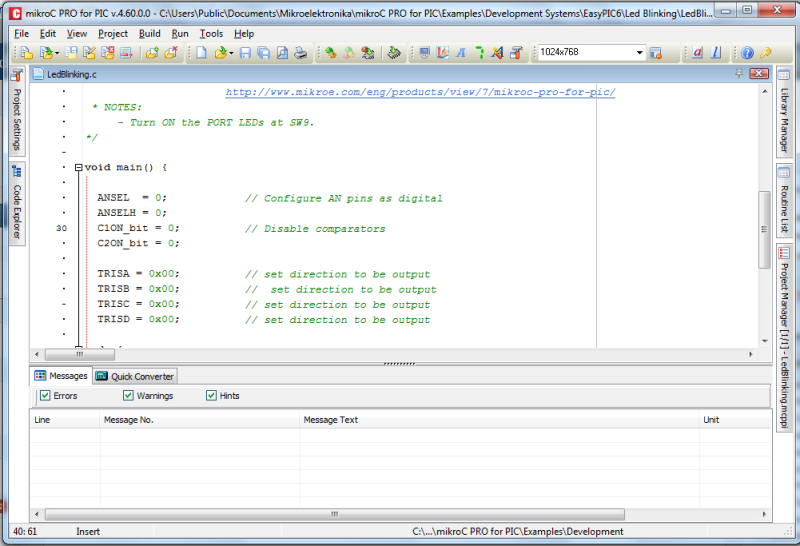
My PIC tutorials and projects use MikroC compiler for firmware development. But I don’t think I ever posted anything on its installation and setup. Today, I am going to show how to install MikroC Pro for PIC (v4.60) on a Windows PC. First of all, download the zipped installation file from here, unzip it and run the setup program. Installation is straightforward. When you first start the MikroC compiler, it opens a LED blinking example project. You can close this project by clicking on ‘Close Project’ under Project menu.

Now, I am going to show you how to create a new project. I will demonstrate with my MikroC code that I wrote for one of my tutorials (Analog to Digital Conversion). First, Do File -> New -> New Project and you will see the Welcome wizard. Click on Next and you will see a wizard for selecting device. Select PIC16F688, and click Next. Then select Device Clock = 4.0 MHz. The third step is to give your project a filename. You can browse to the directory you want and type in the name for your project. I usually create a separate folder for each project so that all the files associated with the project remain inside the folder, including the final output HEX file. The next step is to add files to your project. You can click Next as there are no files that are needed to be included at this point. The fifth step gives you the option to include the built in library routines. Select Include All (Default).

Click Next and you will see the message saying New Project created successfully. Click on Finish, and you will see the programming editor. You will see a default main() function is added to your program editor.

Type in the following program and save it
/*
Lab 5: Analog-to-digital converter
Internal Oscillator @ 4MHz, MCLR Enabled, PWRT Enabled, WDT OFF
Copyright @ Rajendra Bhatt
October 10, 2010
*/
// LCD module connections
sbit LCD_RS at RC4_bit;
sbit LCD_EN at RC5_bit;
sbit LCD_D4 at RC0_bit;
sbit LCD_D5 at RC1_bit;
sbit LCD_D6 at RC2_bit;
sbit LCD_D7 at RC3_bit;
sbit LCD_RS_Direction at TRISC4_bit;
sbit LCD_EN_Direction at TRISC5_bit;
sbit LCD_D4_Direction at TRISC0_bit;
sbit LCD_D5_Direction at TRISC1_bit;
sbit LCD_D6_Direction at TRISC2_bit;
sbit LCD_D7_Direction at TRISC3_bit;
// End LCD module connections
// Define Messages
char message1[] = "ADC Value= ";
char *temp = "0000";
unsigned int ADC_Value;
void main() {
ANSEL = 0b00000100; // RA2/AN2 is analog input
ADCON0 = 0b00001000; // Analog channel select @ AN2
CMCON0 = 0x07 ; // Disbale comparators
TRISC = 0b00000000; // PORTC All Outputs
TRISA = 0b00001100; // PORTA All Outputs, Except RA3 and RA2
Lcd_Init(); // Initialize LCD
Lcd_Cmd(_LCD_CLEAR); // CLEAR display
Lcd_Cmd(_LCD_CURSOR_OFF); // Cursor off
Lcd_Out(1,1,message1); // Write message1 in 1st row
do {
adc_value = ADC_Read(2);
temp[0] = adc_value/1000 + 48; // Add 48 to get the ASCII character value
temp[1] = (adc_value/100)%10 + 48;
temp[2] = (adc_value/10)%10 + 48;
temp[3] = adc_value%10 + 48;
Lcd_Out(1,11,temp);
Delay_ms(2000);
} while(1);
}
In order to set the configuration bits go to Project -> Edit Project. You can see all the options for selecting clock oscillator, WDT, Power up timer, etc. Select the right setting for your project. In this example, I am using the internal RC clock, and so I selected Internal RC No Clock option for the oscillator. If you are using the MCLR reset pin, you should select Enabled option for Master Clear Enable. To compile click on Build -> Build or hit Ctrl + F9. If there are no errors, the HEX file will be generated successfully inside the same project folder and you will see Project Finished Successfully message in the message window, at the bottom.


The HEX file is ready to be downloaded inside the PIC16F688 microcontroller. It’s so easy.
|
|
gude
Excellent site.Bon continuation
thank you
thanks for your perograms 🙂
Pingback: Electronics-Lab.com Blog » Blog Archive » MikroC Pro for PIC : Installation and Setup