PC-based heart rate monitor using Arduino and Easy Pulse sensor
|
|
The heart rate, also referred to as pulse rate, has been recognized as a vital sign since the beginning of medicine, and it is directly related to a person’s cadiovascular health. Today, we are going to make a PC-based heart rate monitor system using an Arduino board and Easy Pulse V1.1 sensor. Easy Pulse is a pulse detecting sensor that uses the principle of transmission photo-plethysmography (PPG) to sense the pulse signal from a finger tip. The sensor output is read by the Arduino board, which then transfers the data to the PC through a serial interface. A PC application is developed using Processing programming language to display the received PPG signal and instantaneous heart rate.

Arduino pulse meter
Brief introduction of Easy Pulse V1.1
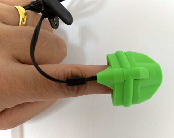
The Easy Pulse sensor is designed for hobby and educational applications to illustrate the principle of photoplethysmography (PPG) as a non-invasive optical technique for detecting cardio-vascular pulse wave from a fingertip. It uses an infrared light source to illuminate the finger on one side, and a photodetector placed on the other side measures the small variations in the transmitted light intensity. The variations in the photodetector signal are related to changes in blood volume inside the tissue. The signal is filtered and amplified to obtain a nice and clean PPG waveform, which is synchronous with the heart beat. For more details, read Easy Pulse V1.1.

Easy Pulse V1.1
Hardware setup
The hardware setup for this project is very simple. All you need is an Easy Pulse V1.1 sensor, an Arduino board, a PC, and few wires. The analog PPG output from Easy Pulse board is fed to an ADC channel of Arduino to convert it into digital counts for further processing. In this project, I am using a Crowduino board, a clone of Arduino Duemilanove, which is manufactured by Elecrow.
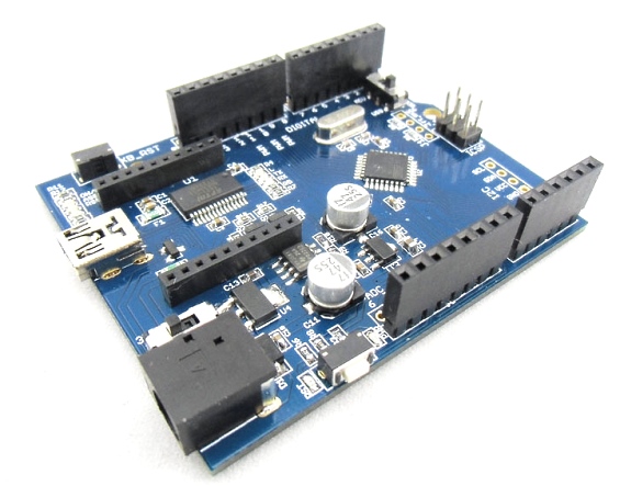
The Crowduino is 100% compatible with Arduino Duemilanuve and comes with additional features. The major difference between Crowduino and other arduino compatible boards is the Crowduino contains a XBee socket. Thus Crowduino not only can adapt all the shields that are compatible with arduino Uno, but also adapts to the Xbee modules from Digi, and any module with the same footprint.
The following picture shows the connections between the Easy Pulse, Crowduino and Power supply. The Easy Pulse sensor operates at +5V. The Enable pin (EN) of Easy Pulse is tied to VCC pin so that the sensor is activated. There is a 2-pin jumper on the Easy Pulse board to do this. The jumper is placed between VCC and EN pin by default, so you don’t need an external wire to do this. The analog output pin (AO) goes to analog input channel A0 of Crowduino. A mini USB cable connects the Crowduino board to the PC. The power supply for Easy Pulse is derived from the Crowduino board.

Arduino and Easy Pulse connections

Easy Pulse meter setup
Arduino Sketch
The programming part of Arduino is very simple. The Arduino takes the ADC samples of the analog PPG signal at 5ms interval and continuously transmits the data to the PC through the USB-UART interface.
/* AnalogReadSerial Reads an analog input on pin 0, prints the result to the serial monitor This example code is in the public domain. */ void setup() { Serial.begin(115200); } void loop() { int sensorValue = analogRead(A0); Serial.println(sensorValue); delay_x(5); } void delay_x(uint32_t millis_delay) { uint16_t micros_now = (uint16_t)micros(); while (millis_delay > 0) { if (((uint16_t)micros() - micros_now) >= 1000) { millis_delay--; micros_now += 1000; } } } |
Download the Arduino Sketch (SendPPGSignal.zip)
PC application
On PC side, we develop an application that reads the incoming ADC samples from the Arduino, and process them to extract the PPG signal and heart rate. The Processing software is used to develop this application. The following flow-chart explains the overall logic of computing the heart rate from the received ADC samples.

Algorithm flowchart for computing heart rate
The PC application first reads 600 consecutive samples sent by Arduino. Since the sampling rate was 5ms, it takes 3 sec to read the 6000 samples. The DC component (minima of 600 samples) is subtracted out from the samples. Next, the range of the samples is computed. If the range is less than 50 counts, the received PPG waveform is very weak, and is considered to be a noise. This could happen when no PPG signal is detected through fingertip (sensor is faulty or disconnected) or the gain of the amplifier on Easy Pulse board is set very low. The gain can be increased through potentiometer P1 on the Easy Pulse board.
If the range of ADC samples is greater than 50, it is considered as a valid PPG signal and is displayed on the PC screen. The samples are scaled to 1-1023 for full swing of display. Next, a 21-point moving average filter is applied to remove the unnecessary high frequency components (usually noise) in the PPG signal. The resulting samples are plotted against time to obtain a clean and smooth PPG waveform. Note that we lose 10 samples at the beginning and 10 samples at the end while applying the moving average filter.
Computing heart rate
The heart beat rate can be computed by knowing the time period of the PPG waveform. For this, we identify three consecutive peaks in the waveform based on where the slope of the curve changes from positive to negative, and the magnitude of the signal is greater than 80% of the maxima of all the samples. Since two consecutive samples are 5ms apart, time difference between any two peaks can be easily computed from their indices (or sequence numbers). Two heart rates are computed from the three consecutive PPG peaks and their average value is displayed as an instantaneous heart rate. The identified peaks are also marked on the display with a cross (X) symbol (see the PPG waveform plotted by the PC application on the computer screen).

PPG Waveform and heart rate displayed on computer screen (click to enlarge)
Download Processing code and exported applications
Note: This software is licensed under a Creative Commons Attribution-ShareAlike 3.0.
Future work
The current version of the Processing application displays the near-real-time PPG waveform and heart rate but does not record anything. There is a lot of room for improvements. Here’s a short list of features that I am seeing for its future release:
- Logging heart rate measurements and PPG samples along with the time-stamp information available from the PC
- Beping sound alarm for heart rates below or above threshold
- Heart rate trend over time, etc.
You can buy both Easy Pulse sensor and Crowduino at Elecrow. US customers can also get Easy Pulse sensor directly from our Tindie store.
|
|
sir, this program work for all peak to peak waveform counting?
also i need deep explanation of this project.
am very new to arduino,i have install the arduino IDE. and i have uploaded the arduino code.i have downloaded the processing code but it refuse to install on my P C. pls……i need u guys help as soon as possible
THANKS
Sir i really want to use this as my final year project…please i need more explanation on this project…and can i use Arduino Uno…
Sir,
I want the detailed procedures of this project.
Help me please..
New to Arduino. Got the easy pulse and downloaded the software. Things worked great once I figured out the Processing part. Thanks!
Any suggestions on how to convert this into a Pulse Oximeter? Any way to add another LED ?
Pingback: 80+ ARDUINO Projects List : - Electronicaa
Is there any way to convert the PPG wave form to a integer value?
Thanks in advance!
the problem during installation of PPG is ” windows cannot find javaw.exe” after install jre nothing is happen with ppg software plz give me a solution for it or a alternate software
software is not installing sir plz give me a alternate
Hello, first of all your project is really good. The problem I have faced while making this project is that when I run the processing sketch, the window appears but it does not display any waveform. Please help…!
Which operating system are you using? Also, try to change the Serial Port number in the processing code.
Hello,
I am using Windows. I tried using the available COM Ports. But it still didn’t work..!
Hi There!
I have made an alternative version and adaption of your circuit (With an LM358 op amp), and processing sketch, that I wanted to share. Hope somebody might find some use for it.
You can find out more in my video on youtube which link is located below, It’s description contain all the links to the project files, hosted on Mediafire, and of course credits back to you too, I have left the comments in your processing sketch untouched.
Hope you have a great day, and thank you very much for everything you share, and making this project work on my end!
To watch the video on youtube go to: https://www.youtube.com/watch?v=rjcHRJN4x8Q
Thanks!
Can we replace the crowduino board with a duemilanove?
Hi everyone,
I want use this easy pulse senor to calculate systolic and diastolic pressures by writing a program in to micro controller taking the comparision between high peek and low peek…I want to do this by connecting easy pulse sensor to arduino board…is it possible to do? any help in this is much appreciated…
Thanks in Advance 🙂
Oh, I thought that I would need to download a pde for the processing code.
Yeah, uh, Raj Bhatt, tnx a million for ANSWERING MY PAST QUESTIONS but I’d really appreciate it if you would just HAVE IT IN YOUR SOFTEST OF HEART to answer me. Pretty please?
What version of pde should I download? Or can I just download the latest version and it will work?
What do you mean by version of pde? The Arduino code should work on just fine with any version of Arduino IDE.
Perfect project !
I decide make small heart monitor for my mom with 1.8″ TFT, ESP8266 and STM32L151 with 2xAAA size.
Thank you for awesome project and sensor !
i’m doing same project could u help me please…
i want the code along with ESP8266 interfacing in it…will u provide me
help me..
Do I need to install an FTDI driver for the crowduino board to work? Every arduino board tutorial website says that about the Arduino Duemilanove and since you said the crowduino board is 100% compatible with the Duemilanove, I felt it might also need d FTDI. But do I need to install it? Plz, I need ur answer ASAP for my final year project. and it’s due in three days.
Do I need to install an FTDI driver for the crowduino board? Every arduino board tutorial website says that about the Arduino Duemilanove and since u said the crowduino board is 100% compatible with the Duemilanove, I felt it might also need d FTDI. But do I need to install it? Plz, I need ur answer ASAP for my final year project. and it’s due in three days.
What version of Processing Development Environment shuld I download 4 d project to work?
Oh, yeah and where is the safest website to download Java Runtime Environment. I also have a question about Elecrow. Is the online store really safe? Please, has anyone ever ordered anything from the online store? I’m really freaked out, because it seems like a phishing website but I don’t want to be judgemental. 🙁
Download JRE from the Java website. Elecrow is a startup and legitimate company which is growing very fast. They are also a distributor of some of our designed products.
I kept surfing the net for info on arduino and found a site that tutored me extensively on the board. At least, I’m no longer confused by the project.
Hi. I would like to enquire about the Elecrow store. I am not really sure about the validity of the online store, although the writer-Raj Bhatt-has been making references to the store. Um, please, has anyone ever ordered anything from the store? I would love to know before I order anything. Please . . .
They are a startup and growing company. They are legitimate company and we have over 30 orders from them so far.
Um, are there versions of ‘pde’s. And if there are, plz, what version should I download before I can download the Processing code?
Rajhendra Bhatt, I would really appreciate it if you could answer me. My project is due in about a week and I’m so confused. I’ve ordered the products from elecrow but I do not understand the software part. I’m still in high school, I need help.
Please, I desperately need help. Firstly, I tried to download the arduino sketch and processing code, but I have been having difficulties. i.e. the folders just won’t open and my computer suspects the folder is viral. Secondly, I do not know which application I should use in creating the codes.
This project was meant for the people who have experiences working with Arduino platform. There are two parts of the software. One is the Arduino part which must be uploaded to Arduino board using Arduino IDE. The second is the PC application and you need to install Processing software to compile and run it.
But when I download the processing code, my antivirus program said it was viral. Why would you be as mean to do that?
It has been downloaded hundreds of times and nobody has ever complained about that.
I have Easy Pue V1.1and Software Easy-Pulse_PPG_Analyzer_V1_0
Error C:\PogramData\Oracle\Java\javapat\javaw.exe
I need Help
Thank You
You need to install JRE on your PC.
Hi,
I am doing this for my project, but the heart pulse didn’t appear on the screen. I got an empty screen when I run he processing code.
Thanks
Thanks for making this. I have been playing with the Easy Pulse Version 1.1 for the last few days, and it seems to have become non-responsive. Can do you know what might have caused this and what I can do to fix it?
Details:
– I have it wired at an Arduino Uno, which is connected to my laptop via USB.
– The wiring is the same as you show in the tutorials: Arduino 5V to the outer-most VCC, easy pulse GND to Arduino GND, easy pulse DO to Arduino pin A0 (I’ve also connected easy pulse AO to this is well).
– I used the Arduino sketch that you provided and modified it to take digital reads of A0. It was working wonderfully earlier tonight: my console log was showing data consistent with my heart beat, and the red LED on the board was blinking in time.
After 1 or 2 hours of testing with the board (it was gathering data almost the whole time) the easy pulse board just stopped sending data and the LED stopped glowing. Adjusting the VR and Gain have no effect.
Can you please help?
Hi Ryan,
I would suggest to use this user guide for testing the sensor:
http://embedded-lab.com/uploads/manuals/EasyPulse_User_Guide.pdf
Make sure Arduino is disconnected from the Easy Pulse while doing this test.
I’m using an Arduino Uno board, and i have Easy Pulse Sensor 1.1, i’ve uploaded the sketch. But the LED still shining bright, it doesn’t blink, i can’t open the ”application.windows64”, my OS is windows 7 64bits. It only opens the ”application.windows32” and doesn’t work as it should. I need some help .-.
First test the sensor only using a 5V power supply. The instructions are provided here:
http://embedded-lab.com/uploads/manuals/EasyPulse_User_Guide.pdf
I connected the easy pulse to the arduino after compiling it its okay but when running the windows 64 Easy_Pulse_PPG_Analyzer_V1_0.exe it says no javaw please respond to my comment asap I need to fix it as soon as possible
I need this for my research please help me as soon as possible
can u please give the coding for this ??!!we r using MC8051 & LTH 1550-01(IR Diode),instead of 3opam,we r using LM324 IC………please help at ur earliest
hi
when i want to install the ”Easy_Pulse_PPG_Analyzer_V1_0.exe” windows says:
‘sorry, windows can not find ‘javaw.exe’. make sure you typed the name correctly, and then try again later.’
how can i solve this problem.
please help me…
I had just the same problem as you, but he ha snot answered my past comments.
Hi, I am connecting the easy pulse, temperature sensor and LCD shield on the arduino uno board. However, there is a lot of noise occur on the value of BPM and Temperature . I have already solve for temperature sensor but i don’t have any idea to solve the noise that affect the BPM value. Any idea on how to solve it?
i try Arduino Sketch , do you have a sketch for arduino without processing, i need a code to have the heart rate bpm on arduino only, i try to make my own code but i don’t understand few things, first you read 600 samples….and after you substract 600 minima (DC component) from the 600 samples, i don’t understand can you explain me? thanks
i tried to upload Easy_Pulse_PPG_Analyzer_V1_0.pde to arduino but it’s impossible to compile it, much error like :
Easy_Pulse_PPG_Analyzer_V1_0:29: error: expected unqualified-id before ‘[‘ token
Easy_Pulse_PPG_Analyzer_V1_0:30: error: expected unqualified-id before ‘[‘ token
Easy_Pulse_PPG_Analyzer_V1_0:41: error: expected unqualified-id before ‘[‘ token
Easy_Pulse_PPG_Analyzer_V1_0:46: error: ‘PFont’ does not name a type
etc……
i use windows, how to install this folder application.windows64, i donwload onlu .pde to arduino, please, can you help me, there is no info in the .pdf, about how to install it ….thanks
i found the solution, you need to download processing and install sketch on arduino for the communication, now i have a blank or black screen but i thinks this is a problem with serial com
You have to set appropriate serial port number in the processing code based on the port number of your Arduino board.
how to visualise the waveform using arduino?? which software we should use
Whenever I try it, it says that gt has not been specified. What do I do?
Use the actual “greater than” symbol instead. See the new code.
Thanks for the help! I have one more question – I wanted to know how to output the data from the Arduino/Easy Pulse to a text file. I need to know as soon as possible because I have a science fair project due. Again, thanks for the help!
Hi,
I am new to both Arduino and Pulse rate measurement. I have connected the Arduino with the Easy Pulse board and executing the application on the Arduino software on PC. I uploaded the program but when I start the Easy Pulse PPG software to see the wave I am getting blank screen. I am using Arduino Due board. Any help on how to get the measurement would be highly appreciated.
Regards,
Chand
Hi Chand,
Make sure you change the Serial Port number appropriate to your PC settings in the PC Processing application.
Wondering if there is any more documentation for the exporter/processing software. I’m having some difficulty getting it set up on my local (ubuntu12.04). Thanks -Lauren
Pingback: En passant sur le web ← Unknow
Pingback: PC-based heart rate monitor using Arduino and Easy Pulse sensor | Make, Electronics projects, electronic Circuits, DIY projects, Microcontroller Projects - makeelectronic.com
Pingback: PC-based heart rate monitor using Arduino and Easy Pulse sensor | Arduino collector blog
Pingback: BLOG | Heart rate monitor using Crowduino and Easy Pulse sensor