STM32 Programming Tips and Tricks
|
|
I remember that once in the beginning I said that I don’t want to buy a programmer/debugger hardware for learning a new MCU like the STM32 and also STM32s already come with built-in bootloader to facilitate programming via USART just like Arduino. Still the second is true. Well what about the first? To my own surprise I actually acquired a number of STM32-related stuffs since the time I started playing and exploring them. I actually bought both ST-Link 1 and 2 programmer-debuggers and several STM32 boards from Waveshare Electronics (http://www.wvshare.com). I believe learning new stuffs is more valuable than anything else.
ST-Link Programmer/Debugger
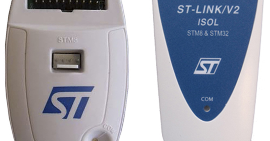
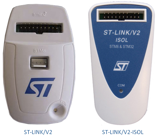
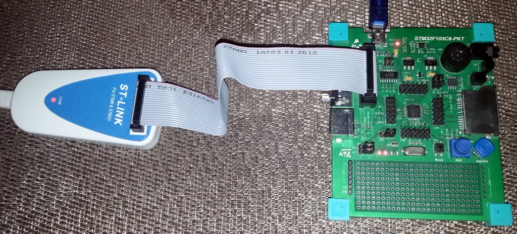
ST-Link 1 (AKA ST-Link) and ST-Link v2 are both basically the same programmer/debugger hardware with some minor exceptions. ST-Link 2 has 5V tolerance for JTAG interface, it has a bicolour status LED and it also has a separate programming interface for STM8 micros unlike ST-Link 1. There is also an ISOL version of ST-Link2 that galvanically isolates it from its target using optoelectronics.
I’m not going to recite all the feature chatters of ST-Link programmers here. All I’ll say is if you want a device that can save your time and efforts from all the procedure involved with serial bootloader, do pro-level works with STM8/STM32 and debug your codes then you should consider having a ST-Link programmer-debugger. It doesn’t matter much which version it is. For more info on ST-Link programmer-debuggers refer to these links:
http://www.st.com/web/catalog/tools/FM146/CL1984/SC720/SS1454/PF219866
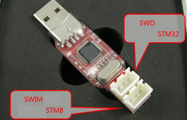
There cheap and compact clone variants of ST-Link programmers too but I won’t recommend them simply because they don’t have easy plug-in JTAG interface cable, they have poor documentation and they are not genuine. By the way I’m not telling not to buy those. I leave it to the reader. In my experience buying a genuine programmer is always a long-run benefit while keeping a clone alongside the genuine one is like bonus.
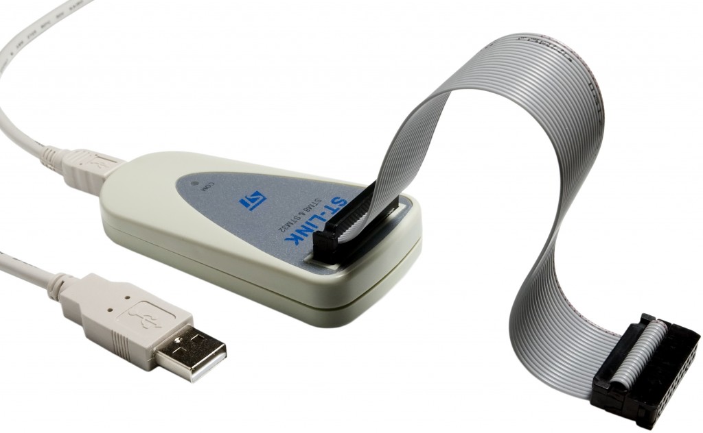
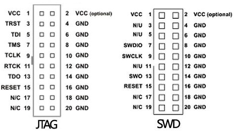
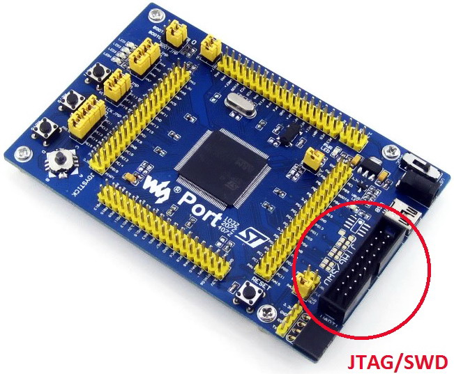
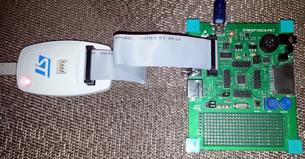
Hardware driver installations are not complicated and I’m thus skipping this part too. Anyone familiar with Windows environment will figure out everything related to software and driver installation. JTAG/SWD (Serial Wire Debug) interface terminal is available in most STM32 development boards and can be located by a distinct 20 pin black header that looks like a PC’s IDE cable connector. ST-Link connects with a STM32 via JTAG/SWD interface. Just be sure that both ends of the header connect according to the notches.
Waveshare Electronics make a variety of STM32 development boards. Their boards are as much as robust as that of MikroElektronika’s. A salient feature of their boards unlike other ARM development board available in the market is the modular plug-in system for connecting external hardware like nRF24L01 modules, TFT displays, flash memories, RTC, etc. In terms of board layout, vivid labelling and user-friendly orientation, I guess Waveshare’s boards are just awesome. I personally use and recommend Waveshare products for their outstanding quality.
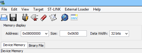
The software interface for both ST-Link 1 and 2 is STM32 St-Link Utility. This software is for STM32 micros only. STM8 micros need another software to use these programmers. Since we are currently dealing with STM32 micros, we’ll be discussing about STM32 St-Link Utility only.
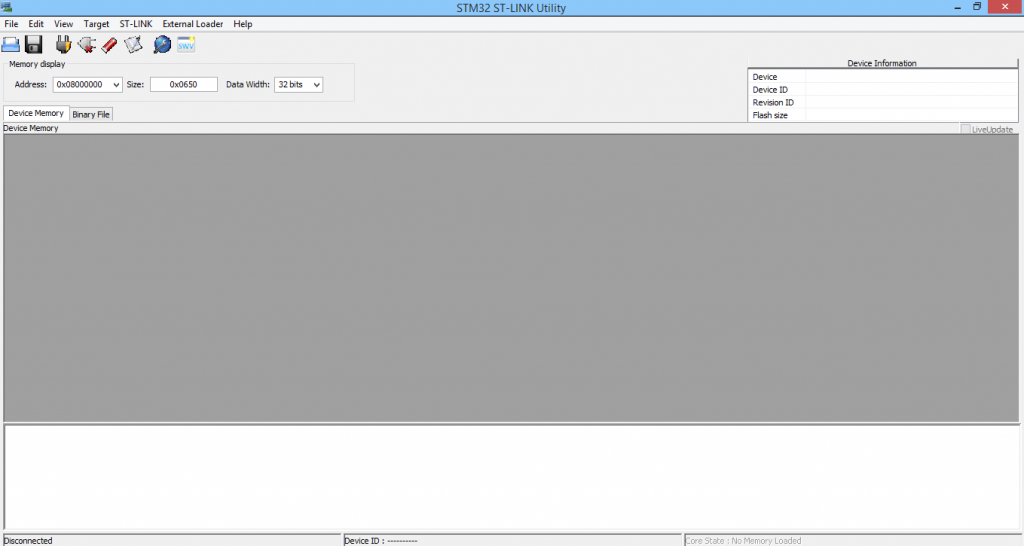
The GUI is pretty straight forward. Just like any programmer GUI it has iconic buttons for various tasks. However unlike most other programmer GUI we’ll need to connect to the programmer hardware manually using the connect button (plug like icon).
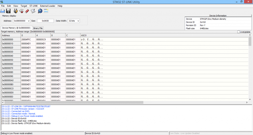
Once connected the programmer hardware will communicate with the target micro and find out details about it. These details include flash memory size, page protection settings, fuses, device series/family and other stuffs. When there’s a successful connection, the LED in ST-Link hardware starts flashing randomly. There’s also a disconnect button to terminate the communication between target MCU and ST-Link.
Just like any other programmer GUI we can browse for bin/hex files to be imported to or exported from the target MCU, set fuse settings and erase its memories. Thus there is nothing exceptionally different. A cool feature of ST-Link programmers is to be able to debug a code step-by-step.
Check out the video links to see how they work:
ST-Link 1: https://www.youtube.com/watch?v=tcU1HwI_3Mk
ST-Link v2: https://www.youtube.com/watch?v=j5L41eJ0UNc.
Please be noted that using the programmer doesn’t cause any problem with serial bootloader. If a STM32 chip is set to full erase, the bootloader is still retained. As per ST’s documentations mass-erase doesn’t affect information blocks. Thus there are always two ways of programming a STM32 micro. This is very useful because even if for some reason your ST-Link gets damaged and unable to program, you still have serial bootloader option to get the job done.
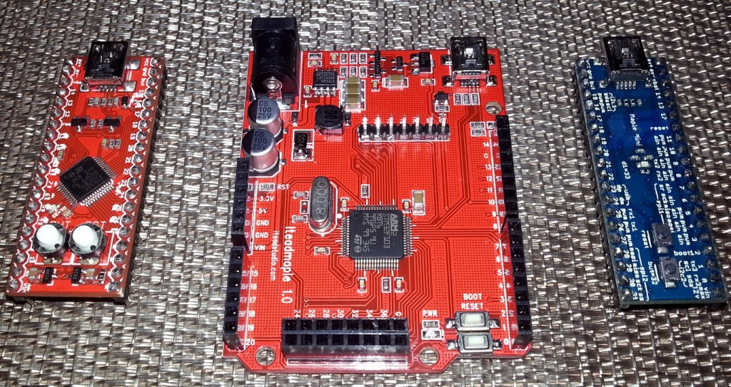
Leaf Maple Boards
Many people from the Arduino community are using Leaf Maple boards as 32-bit alternatives to 8-bit AVR core based mainstream Arduino boards apart from Arduino Zero and Arduino Due. 32-bit micros as we know are far more powerful than 8-bit ones in every aspect. Leaf Maple boards are designed with STM32F10x series micros, specifically with STM32F103s and have Arduino-like form factor. Thus Arduino shields can be used easily. Maple boards got my attention not because they are based on Arduino-like coding or have Arduino-like features but for the fact that I can use my existing array of Arduino shields to make stuffs with STM32 micros easily and without any new investment on hardware. For instance I have a 2.4 inch TFT touch display shield for Arduino Uno, now I can use that for playing with STM32 too. This helped me to avoid buying and fabricating a new TFT touch display just for STM32s. One thing I like about Arduino platform is the ease it offers in formulating a prototype design. Many of my prototypes are based on Arduino platform and it is there I enjoy it much. With Maple boards the fun gets greater. However I’m not willing to use those boards like Arduinos because Arduino platform is not a professional one. I want them to be able to work without the Arduino framework. To get this done we can use either ST-link programmers or the serial bootloader.
There are several key differences between Maple boards and typical STM32 development boards and these are:
- Absence of standard 20 pin JTAG/SWD headers in Maple boards.
- Pin orientation and naming convention.
- Absence of boot jumpers in Maple boards
- Board size, layout and form-factor.
- Maple is based on STM32F10x series micros. There’s no support for other STM32 micros.
- Maple comes with its own USB bootloader that can’t be used without DFU enumeration process.
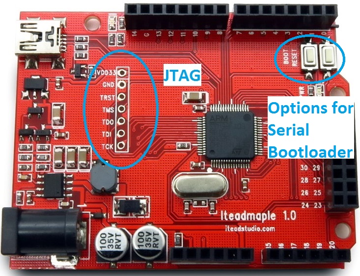
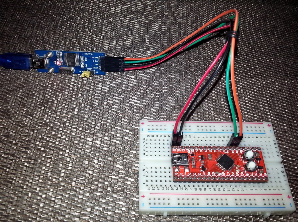
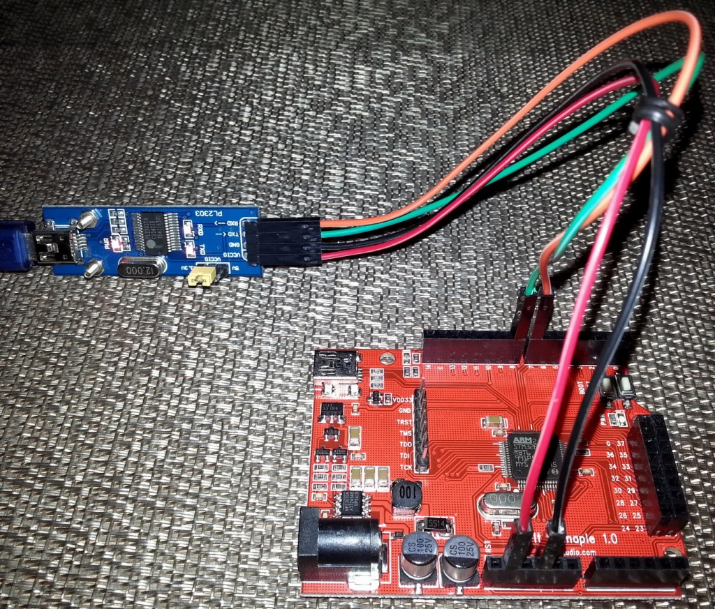
From our previous knowledge on STM32’s serial booloader we know that we only have to change Boot 0 pin state in order to enter serial bootloader mode. Maple boards have one extra button apart from reset button. Usually this button is named either as BUT or BOOT as per Leaf Maple’s design. This button is attached to the Boot 0 pin of STM32. First connect the TX1, RX1 and power pins of your Maple board with a USB-serial converter. Remember that STM32s operate with 3.3V power and so avoid using a USB-serial converter that operates above 3.3V. According to Leaf Maple’s documentations TX1 and RX1 pins are located at pins D26 and D25 respectively for Maple Mini and at D7 and D8 respectively for Maple board. Secondly to enter the serial bootloader mode we’ll have to go according to the sequence below:
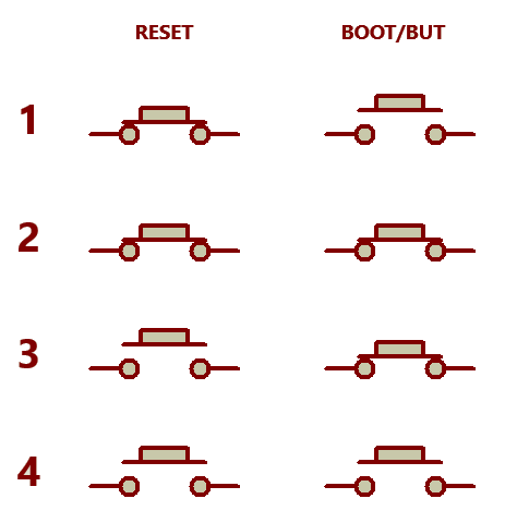
- Hold the Reset button first and then the Boot/BUT button.
- Release the Reset button first and then the Boot/BUT button.
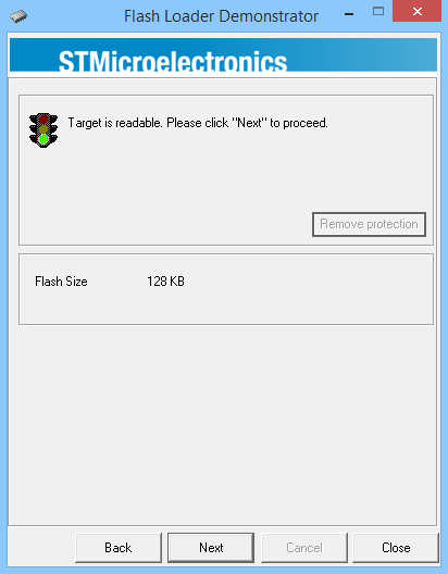
- Run the ST’s Flash Loader Demo software.
- Provided that the settings of that Flash Loader Demo GUI are set properly, hit the Next button and continue as usual.
Please be noted that while in serial bootloader mode no LED on a Maple board will be blinking. Only the power LED (if any) will remain turned on. The board will behave as if it is unpowered or dead. This is normal and so there’s no reason to worry.
If you have missed my post on STM32’s serial bootloader mode then check out this link:
http://embedded-lab.com/blog/?p=8764.
To avoid confusion, here are the above described four bootloader steps visually shown:
I have accessed my Maple boards and here are the videos and photos of them at action:
Video links:
Maple Mini: https://www.youtube.com/watch?v=9VwLyCkj95U.
Maple Board: https://www.youtube.com/watch?v=__gWcS-o_iU.
Happy playing with STM32s.
Repository: https://github.com/sshahryiar/STM32-Tutorials
Author: Shawon M. Shahryiar
https://www.youtube.com/c/sshahryiar
|
|