STM32’s internal RTC
|
|
A Real Time Clock (RTC) is a timing element dedicated for keeping time. In many applications, especially where precise timed-operations are needed to be performed, a RTC is a very useful tool. Examples of such applications apart from clocks and watches include washing machines, medicine dispensers, data loggers, etc. Basically a RTC is a timer-counter but unlike other timers of a MCU it is much more accurate. Previous to this post, we explored STM32 timers but those were useful for applications like PWM generation, time-bases and other waveform-related tasks. Those were not suitable for precise time-keeping. In most 8-bit MCUs like the regular PICs and AVRs, there are no built-in RTC modules and so we need to use dedicated RTC chips like the popular DS1302 or PCF8563 when we need an on-board precise time-keeping device. Those chips also need some additional circuitry, wiring and circuit board space. At present, however, most modern MCUs come packed with literally every possible hardware a designer may think of. It is only up to a designer to decide which resources to use from a modern-era micro to meet a specific design goal. Gone are the days when MCUs were manufactured for application specific requirements and also gone are the days of implementing and involving multiple assets in a design. Thus cost, time and space are dramatically reduced, resulting smarter, sleeker and smaller affordable devices. Fortunately STM32s are in that list of those modern era microcontrollers. STM32 MCUs come with built-in RTC modules that require no additional hardware support. This tutorial covers basic features of STM32’s internal RTC and how to use it for time-keeping applications.
Feature of STM32 RTC Block
The embedded RTC of a STM32 micro is an independent binary-coded-decimal (BCD) timer counter. The RTC core consists of counters, prescalers, clock dividers, alarm data registers, etc. Like with any standard RTC chip, the embedded RTC can be used to provide a full-featured software-based calendar along with alarm functions. However more needs to be done on the software end rather than the hardware end. When using RTC chips, it is only required to read or write individual date-time registers. In a STM32 micro, we need to do more than that as no separate date-time registers exist.
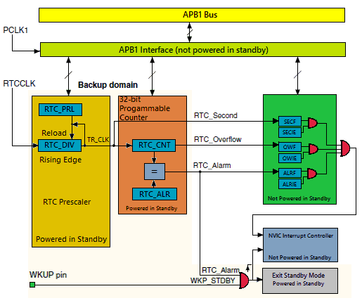
Resetting or waking up the MCU from a sleep/standby mode does not reinitializes time once set. It gets even better if there is a battery backup on battery backup (VBAT) pin. All VDDs of a STM32 can be turned off or in other words the entire MCU core can be fully shut down but the battery backup keeps the RTC and the backup domain running. Thus time is not varied or lost during powered down and sleep modes. Key features of the STM32 embedded RTC are highlighted below:
- Programmable prescaler: division factor up to .
- 32-bit programmable counter for long-term measurement
- Two separate clocks: PCLK1 for the APB1 interface and RTC clock.
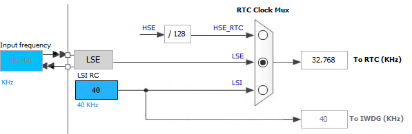
- The RTC clock source could be any of the following ones
- HSE clock divided by 128.
- LSE oscillator clock.
- LSI oscillator clock.
- Two separate reset types:
- The APB1 interface is reset by system reset.
- The RTC core is reset only by a Backup domain reset.
- Three dedicated maskable interrupt lines:
- Alarm interrupt, for generating a software programmable alarm interrupt.
- Seconds interrupt, for generating a periodic interrupt signal with a programmable period length (up to 1 second).
- Overflow interrupt, to detect when the internal programmable counter rolls over to zero.
Functional Description
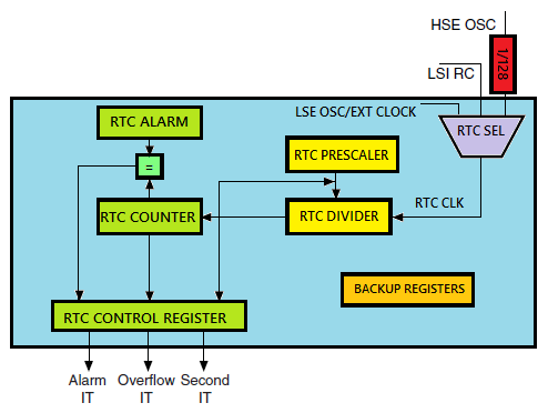
Shown below is the block diagram of the embedded RTC for a typical STM32F10x microcontroller.
The RTC comprises of two major components. The first is the APB1 bus interface. The APB1 bus interface consists of clock dividers and is used to connect with APB1 bus. This interface also consists of a set of 16-bit registers that can be read/written by APB1 bus operations.
The other component is the RTC core. It consists of a group of programmable counters divided into two modules. The first module is the RTC prescaler module. This module generates a programmable time base of one second (TR_CLK) by using a 20-bit programmable divider. The other module is a 32-bit wide programmable counter that is used to keep counts of seconds. Since it is 32-bit wide, with a TR_CLK period of one second, it can record up to 4,294,967,296 seconds or roughly a century – a pretty big time for any machine or a human lifetime.
There are registers for alarms which work in a similar manner as compare match interrupt in a timer. Whatever stored in the alarm registers is compared with the values in the counter registers. An alarm event occurs when both register sets have the same value.
The RTC core is totally independent of the RTC APB1 interface just like the Independent Watchdog Timer (IWDG). RTC registers, counters, alarms and flags are accessible via APB1 interface but the counter registers are updated by a separate RTC clock. As illustrated in the block diagram, the RTC core keeps functioning even if the APB1 bus is unpowered. This is only possible with power supply backup using a battery or a supercapacitor.
RTC Registers
The good part of RTC registers is the fact that most of them are 16-bit wide while the rest are even less than a byte wide. There are two RTC control registers which set RTC properties. The rest of the stuffs are counters and clock dividers. Check the RTC register map below:
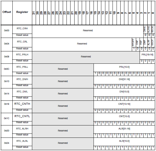
The RTC_CRH register is the first control register which is responsible for setting up interrupts related to the RTC module. There are three types of interrupts and these are alarm, overflow and second interrupt.
The other control register is the RTC_CRL. This register consists of several flags that trigger on events like counter overflow, alarm, RTC status, etc.
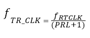
Then we see the RTC prescaler load registers as RTC_PRLL and RTC_PRLH. Together they are 20-bit wide. These two registers are used to divide the RTC clock source frequency. These registers are write protected and special steps are needed to disable this protection. In my example I used an external 32.768 kHz crystal oscillator and so I loaded 32,767 in these registers to get one second. Thus the formula for getting TR clock (TR_CLK) frequency can be realized as:
 Next are the RTC divider registers – RTC_DIVL and RTC_DIVH. The purpose of these registers is to obtain a higher resolution clock than the second count, e.g. 100ms. These are not usually used.
The RTC counter registers – RTC_CNTL and RTC_CNTH are the most important registers as they keep the count of the seconds or in other words time. These registers are each 16-bit wide. Once set these registers return current time. Writing these registers is only possible by entering configuration mode.
Finally there are two 16-bit registers dedicated for alarm. RTC_ALRL and RTC_ALRH hold alarm time data. This set of registers is just like a typical data registers or RAM location. When an alarm is set the alarm register values are compared with RTC counter register values. An alarm is triggered when the values in these registers match. Again modification to these registers is only possible in configuration mode.
Apart from the registers within the RTC block, we also need to deal with the registers of the backup block. The backup domain of a STM32 MCU is somewhat like an EEPROM memory but it is not essentially a true EEPROM memory as it needs battery backup on VBAT pin to hold data. The backup domain consists a total of 42 data registers, each 16-bit wide. These are usually used to retain user data when a STM32 micro’s main core is powered down or in standby mode. Thus backup data registers can be realized as battery-backed RAM storages.
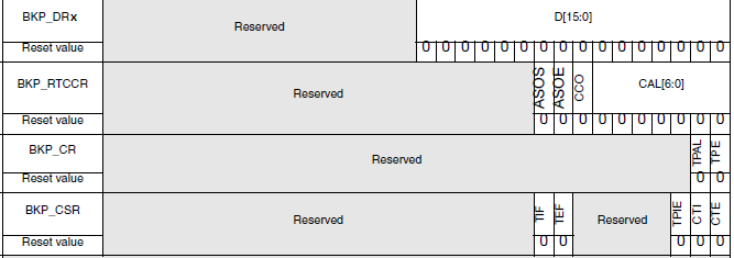
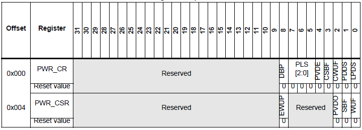
Apart from these backup domain registers we will be needing some other registers for additional functionalities of the backup and the RTC block. Those registers won’t be needing for now and won’t be discussed here. We’ll be needing the Power Control (PWR) registers for disabling backup domain write protect scheme. Power control registers will be dealt separately in details in another post.
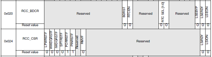
Just as we configure the main HSE/HSI/ PLL clock, we will be configuring the LSE/LSI clock. We will be needing to configure some registers of the Reset and Clock Control (RCC) block for this purpose. RCC_BDCR and RCC_CSR registers will be needed to select RTC clock source and enable low speed (LSI and LSE) clock sources.
In my version of SPL, I took care of all of these stuffs. We just have to apply them.
Procedure to Configure the RTC Block
-
- Firstly power up the STM32 micro and initialize other required hardware like LCD, keypad and other stuffs.
-
- We already know that right after reset or power on, the backup domain and the RTC are both disabled. Furthermore the backup registers are kept in a write protected state to avoid any parasitic write. Thus we need to enable power and backup interfaces by setting PWREN and BKPEN bits in the reset and clock control APB1 interface enable register (RCC_APB1ENR).
-
- Next we need to disable the backup register write protection using the DBP bit of PWR_CR When we configure the RTC for the first time, we must reset backup registers and also important RTC registers like the RTC counter register to avoid any unwanted parasitic values
-
- The next thing we need to do is to select the clock source that will be responsible for keeping time. We will enable it and we should give it some time to stabilize. Of the three possible clock sources I preferred the external 32.768 kHz crystal oscillator clock (LSE) because it is the usual procedure. Using LSE clock requires that we use a high quality crystal for accurate timing.
-
- After every major write operation on RTC registers we must poll if the last write operation is completed or terminated. This is done by polling RTOFF bit in RTC_CRL This is very important.
-
- Before configuring the RTC, we need to enter configuration mode by setting CNF flag in RTC_CRL After configuration we need to clear this flag to avoid further changes.
-
- One major configuration is setting the values of RTC_PRL registers because on their values it depends how fast or slow the RTC clock runs. Since I used the 32.768 kHz LSE clock PRL registers are loaded with 32767 to get one second interval interrupt. Why it is this value has already been explained. We may further calibrate this clock but usually it is not required. If it is required we can further use the RTC divider registers to acquire a clock of more resolution.
-
- I have always preferred interrupt methods over polling methods for several reasons and advantages, and so here to get RTC clock ticks, I used RTC second interrupt. The RTC interrupt for STM32F10x micros has one interrupt vector address. After an interrupt event we will just check the interrupt flags and find out which event invoked the interrupt and then clear it.
- To make sure that the RTC is configured only once during the first initialization and not repeatedly reconfigured after every reset or power down event, we will be storing an arbitrary value of our choice in a backup data register. I used 0x9999. We will put this value once the RTC has been completely configured and apply write protection. Since backup data registers mimic are battery-backed data storages, unless the backup battery is removed the RTC initialization and working are retained. With this condition, if a reset or power down event occurs the program restarts from the very beginning and check the backup register value. If the value is not what has been set after initialization, the RTC is reinitialized or otherwise the RTC initialization is skipped and only its interrupts are enabled.
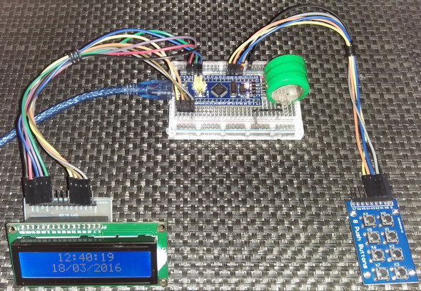
Hardware setup
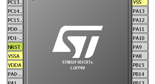
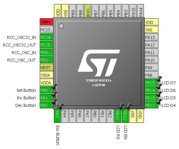
The hardware setup for this example is very simple. For this demo I used a STM32F103C8T6 micro, a 2×16 alphanumerical LCD connected to GPIOB port pins and four push buttons connected to GPIOA port pins. The buttons are used for setting time. Since I used LSE clock, a 32.768 kHz clock crystal is connected to PC14 and PC15 pins. I also used an 8MHz external crystal for RCC. Using PLL, the clock speed is multiplied to generate 72 MHz system clock. A 3.6V, 250mAH backup lithium ion battery is connected to the VBAT pin. This keeps the backup domain and the RTC core powered.
The RCC’s internal setup is as follows:
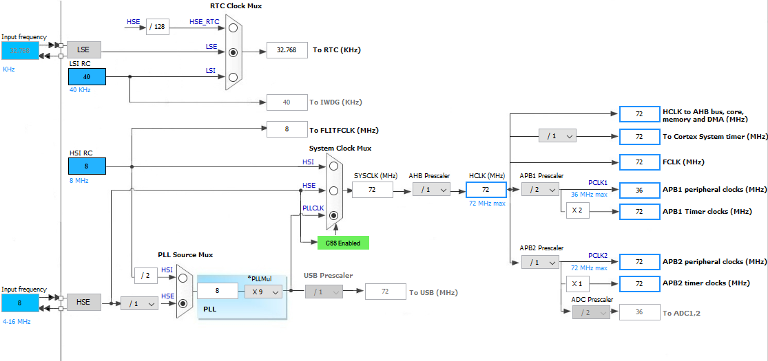
Except the RTC clock source selection, the rest of the RCC settings are done with MikroC compiler’s clock configuration tool. One caution before coding is that the RTC clock should be at least 4 times slower than PCLK1.
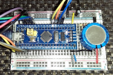
After going through the basics till now, we can understand the necessity for a power supply backup. This backup can be achieved in various ways. Two common backup sources are:
- Battery – small NiMH, NiCd, Li ion or Lipo cells.
- Supercapacitor – 0.22F to 1F.
I used the former method. The latter method is suitable for short power interruption. I tested this form of backup for an hour and it worked perfectly. The former works even better. Since the RTC and the backup module consumes very low power, the backup power source slowly discharges. Supercaps will discharge much faster with rapid fall of voltage level than batteries and so they are not intended as long-time backup. However supercaps have long life and need lesser replacements than batteries.
ST recommends that VBAT pin should either be tied to a backup source or to VDD. VBAT pin however doesn’t charge the backup power source. Thus we need a mechanism to charge the source when VDD is available. Here are two techniques:
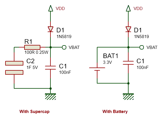
In both methods, diode D1 is a low-drop diode, preferable a switching diode like the 1N5819 Schottky diode. This diode charges the backup source with VDD source as well as power the VBAT pin with VDD when available. The allowed VBAT voltage range is 1.8V – 3.6V. With this diode in place, the voltage on VBAT pin never exceeds the maximum allowed value. VBAT will typically see about 3Vs. Capacitor C1 stabilizes the backup source and reduces tiny voltage ripples if any.
When we use supercaps instead of batteries, we need to be careful because a fully discharged supercap behaves like a temporary short circuit. When connected to a power source, it will draw high currents to rapidly charge itself, creating a temporary power surge as well as voltage dip. If unchecked this power surge may kill the onboard regulator that powers the MCU. Thus to prevent this from happening resistor R1 is used. This resistor slowly charges the supercap. With this arrangement it takes about a minute to charge the supercap. Any power interruption within this time will cause loss of back register data as well as affect functioning of the RTC.
Coding the RTC
Coding the STM32 embedded RTC is not very easy. A variety of methods can be applied. The code I wrote is for a 24-hour clock with a calendar starting from epoch to the end of the year 2099. My code for the RTC can be realized as three major portions:
Configuration
The RTC is configured as per procedure stated in the last section. The RTC_init function does the RTC configuration part. If the configuration is successful 0 returned otherwise 1 is returned to indicate that the LSE is not working properly. If LSE clock fails to stabilize within 250ms, it is considered that the LSE clock is having some problem and further coding is skipped. The RTC counter is not loaded during the initial configuration session but after that with set_RTC function.
unsigned char RTC_init()
{
unsigned char timeout = 0;
if(BKP_DR1 != rtc_access_code)
{
enable_power_control_module(true);
enable_backup_module(true);
disable_backup_domain_write_protection(true);
set_backup_domain_software_reset(true);
set_backup_domain_software_reset(false);
bypass_LSE_with_external_clock(false);
enable_LSE(true);
while((LSE_ready() == false) && (timeout < 250))
{
timeout++;
delay_ms(10);
};
if(timeout > 250)
{
return 1;
}
select_RTC_clock_source(LSE_clock);
enable_RTC_clock(true);
while(get_RTC_operation_state() == false);
while(get_RTC_register_sync_state() == false);
enable_RTC_second_interrupt(true);
while(get_RTC_operation_state() == false);
set_RTC_configuration_flag(true);
set_RTC_prescalar(32767);
set_RTC_configuration_flag(false);
while(get_RTC_operation_state() == false);
BKP_DR1 = rtc_access_code;
disable_backup_domain_write_protection(false);
set_RTC(cal_year, cal_month, cal_date, cal_hour, cal_minute, cal_second);
}
else
{
while(get_RTC_register_sync_state() == false);
enable_RTC_second_interrupt(true);
while(get_RTC_operation_state() == false);
}
NVIC_IntEnable(IVT_INT_RTC);
return 0;
}
Setting/Writing the Time Parameters
After initialization or at any instance we may need to set current time and this is done by using the set_RTC function. This function has 6 arguments for 6 date-time parameters – year, month, date, hour, minute and second. In my RTC coding, the calendar time starts from epoch. As per MikroC’s help documentation:
“Originally it was defined as the beginning of 1970 GMT. (January 1, 1970 Julian day) GMT, Greenwich Mean Time, is a traditional term for the time zone in England.”
The calendar becomes invalid after the year 2099 – roughly about a century from time of writing this article. Since the RTC counts seconds and not actual date-time parameters individually, every time parameter is calculated as second equivalents. For instance 3,600 seconds equal one hour and 86,400 seconds is equal to a complete 24-hour day. During calculations we need to take leap years into account or otherwise the time calculations will be imperfect after some years.
After having found the present second count, the count value is loaded in the RTC counter registers. We need to enter in configuration mode for setting this count value and we need to exit this mode at the end of setting it. From this time forth, the RTC starts counting time. Whatever it then returns is the current time.
void set_RTC(unsigned int year, unsigned char month, unsigned char date, unsigned char hour, unsigned char minute, unsigned char second)
{
unsigned int i = 0;
unsigned long counts = 0;
if(year > 2099)
{
year = 2099;
}
if(year < 1970)
{
year = 1970;
}
for(i = 1970; i < year; i++)
{
if(check_for_leap_year(i) == 1)
{
counts += 31622400;
}
else
{
counts += 31536000;
}
}
month -= 1;
for(i = 0; i < month; i++)
{
counts += (((unsigned long)month_table[i]) * 86400);
}
if(check_for_leap_year(cal_year) == 1)
{
counts += 86400;
}
counts += ((unsigned long)(date - 1) * 86400);
counts += ((unsigned long)hour * 3600);
counts += ((unsigned long)minute * 60);
counts += second;
enable_power_control_module(true);
enable_backup_module(true);
disable_backup_domain_write_protection(true);
set_RTC_configuration_flag(true);
set_RTC_counter(counts);
set_RTC_configuration_flag(false);
while(get_RTC_operation_state() == false);
disable_backup_domain_write_protection(false);
}
Reading the Time Parameters
Reading time is just the opposite of setting it. The RTC counter registers are read and the current count is stored in a variable. From this variable, the code first find the number of days that has passed since epoch. Based on this info, the code findd current year and then current month, taking leap years into account in both steps. Finally we get date and time parameters. Reading time doesn’t need any special privilege as like in writing time parameters.
void get_RTC()
{
unsigned int temp1 = 0;
static unsigned int day_count;
unsigned long temp = 0;
unsigned long counts = 0;
counts = RTC_CNTH;
counts <<= 16;
counts += RTC_CNTL;
temp = (counts / 86400);
if(day_count != temp)
{
day_count = temp;
temp1 = 1970;
while(temp >= 365)
{
if(check_for_leap_year(temp1) == 1)
{
if(temp >= 366)
{
temp -= 366;
}
else
{
break;
}
}
else
{
temp -= 365;
}
temp1++;
};
cal_year = temp1;
temp1 = 0;
while(temp >= 28)
{
if((temp1 == 1) && (check_for_leap_year(cal_year) == 1))
{
if(temp >= 29)
{
temp -= 29;
}
else
{
break;
}
}
else
{
if(temp >= month_table[temp1])
{
temp -= ((unsigned long)month_table[temp1]);
}
else
{
break;
}
}
temp1++;
};
cal_month = (temp1 + 1);
cal_date = (temp + 1);
}
temp = (counts % 86400);
cal_hour = (temp / 3600);
cal_minute = ((temp % 3600) / 60);
cal_second = ((temp % 3600) % 60);
}
Lastly an interrupt is used to update time parameters as well as clear interrupt flags.
void RTC_ISR()
iv IVT_INT_RTC
ics ICS_AUTO
{
if(get_RTC_second_flag_state() == true)
{
update_time = 1;
clear_RTC_second_flag();
}
clear_RTC_overflow_flag();
while(get_RTC_operation_state() == false);
}
In complete code, there are functions for displaying time parameters in the LCD easily and efficiently. The four buttons connected to the GPIOA port pins are for entering settings mode, increasing a parameter, decreasing a parameter and finally to accept the new value of the parameter that has been selected for alternation. Here’s the complete code:
#include "RTC.h"
#include "GPIO.h"
#include "BACKUP.h"
#define rtc_access_code 0x9999
#define set_button_pin 0
#define inc_button_pin 1
#define dec_button_pin 2
#define esc_button_pin 3
sbit LCD_RS at GPIOB_ODR.B10;
sbit LCD_EN at GPIOB_ODR.B11;
sbit LCD_D4 at GPIOB_ODR.B12;
sbit LCD_D5 at GPIOB_ODR.B13;
sbit LCD_D6 at GPIOB_ODR.B14;
sbit LCD_D7 at GPIOB_ODR.B15;
const unsigned char month_table[12] = {31, 28, 31, 30, 31, 30, 31, 31, 30, 31, 30, 31};
unsigned char cal_hour = 0;
unsigned char cal_date = 1;
unsigned char cal_month = 1;
unsigned char cal_minute = 0;
unsigned char cal_second = 0;
unsigned int cal_year = 1970;
bit update_time;
void setup_mcu();
void setup_GPIOs();
unsigned char RTC_init();
void get_RTC();
void set_RTC(unsigned int year, unsigned char month, unsigned char date, unsigned char hour, unsigned char minute, unsigned char second);
unsigned char check_for_leap_year(unsigned int year);
void show_value(unsigned char x_pos, unsigned char y_pos, unsigned char value);
void show_year(unsigned char x_pos, unsigned char y_pos, unsigned int value);
unsigned int change_value(unsigned char x_pos, unsigned char y_pos, signed int value, signed int value_min, signed int value_max, unsigned char value_type);
void settings();
void RTC_ISR()
iv IVT_INT_RTC
ics ICS_AUTO
{
if(get_RTC_second_flag_state() == true)
{
update_time = 1;
clear_RTC_second_flag();
}
clear_RTC_overflow_flag();
while(get_RTC_operation_state() == false);
}
void main()
{
setup_mcu();
lcd_out(1, 7, ": :");
lcd_out(2, 6, "/ /");
while(1)
{
settings();
if(update_time)
{
get_RTC();
show_value(5, 1, cal_hour);
show_value(8, 1, cal_minute);
show_value(11, 1, cal_second);
show_value(4, 2, cal_date);
show_value(7, 2, cal_month);
show_year(10, 2, cal_year);
update_time = 0;
}
};
}
void setup_mcu()
{
unsigned char i = 0;
setup_GPIOs();
Lcd_Init();
Lcd_Cmd(_LCD_CLEAR);
Lcd_Cmd(_LCD_CURSOR_OFF);
Lcd_Out(1, 4, "STM32 RTC.");
i = RTC_init();
switch(i)
{
case 1:
{
lcd_out(2, 1, "RTC init. failed");
while(1);
}
default:
{
lcd_out(2, 1, "RTC init success");
delay_ms(2000);
break;
}
}
Lcd_Cmd(_LCD_CLEAR);
}
void setup_GPIOs()
{
enable_GPIOA(true);
setup_GPIOA(set_button_pin, digital_input);
enable_pull_up_GPIOA(set_button_pin);
setup_GPIOA(inc_button_pin, digital_input);
enable_pull_up_GPIOA(inc_button_pin);
setup_GPIOA(dec_button_pin, digital_input);
enable_pull_up_GPIOA(dec_button_pin);
setup_GPIOA(esc_button_pin, digital_input);
enable_pull_up_GPIOA(esc_button_pin);
enable_GPIOB(true);
setup_GPIOB(10, (GPIO_PP_output | output_mode_medium_speed));
setup_GPIOB(11, (GPIO_PP_output | output_mode_medium_speed));
setup_GPIOB(12, (GPIO_PP_output | output_mode_medium_speed));
setup_GPIOB(13, (GPIO_PP_output | output_mode_medium_speed));
setup_GPIOB(14, (GPIO_PP_output | output_mode_medium_speed));
setup_GPIOB(15, (GPIO_PP_output | output_mode_medium_speed));
}
unsigned char RTC_init()
{
unsigned char timeout = 0;
if(BKP_DR1 != rtc_access_code)
{
enable_power_control_module(true);
enable_backup_module(true);
disable_backup_domain_write_protection(true);
set_backup_domain_software_reset(true);
set_backup_domain_software_reset(false);
bypass_LSE_with_external_clock(false);
enable_LSE(true);
while((LSE_ready() == false) && (timeout < 250))
{
timeout++;
delay_ms(10);
};
if(timeout > 250)
{
return 1;
}
select_RTC_clock_source(LSE_clock);
enable_RTC_clock(true);
while(get_RTC_operation_state() == false);
while(get_RTC_register_sync_state() == false);
enable_RTC_second_interrupt(true);
while(get_RTC_operation_state() == false);
set_RTC_configuration_flag(true);
set_RTC_prescalar(32767);
set_RTC_configuration_flag(false);
while(get_RTC_operation_state() == false);
BKP_DR1 = rtc_access_code;
disable_backup_domain_write_protection(false);
set_RTC(cal_year, cal_month, cal_date, cal_hour, cal_minute, cal_second);
}
else
{
while(get_RTC_register_sync_state() == false);
enable_RTC_second_interrupt(true);
while(get_RTC_operation_state() == false);
}
NVIC_IntEnable(IVT_INT_RTC);
return 0;
}
void get_RTC()
{
unsigned int temp1 = 0;
static unsigned int day_count;
unsigned long temp = 0;
unsigned long counts = 0;
counts = RTC_CNTH;
counts <<= 16;
counts += RTC_CNTL;
temp = (counts / 86400);
if(day_count != temp)
{
day_count = temp;
temp1 = 1970;
while(temp >= 365)
{
if(check_for_leap_year(temp1) == 1)
{
if(temp >= 366)
{
temp -= 366;
}
else
{
break;
}
}
else
{
temp -= 365;
}
temp1++;
};
cal_year = temp1;
temp1 = 0;
while(temp >= 28)
{
if((temp1 == 1) && (check_for_leap_year(cal_year) == 1))
{
if(temp >= 29)
{
temp -= 29;
}
else
{
break;
}
}
else
{
if(temp >= month_table[temp1])
{
temp -= ((unsigned long)month_table[temp1]);
}
else
{
break;
}
}
temp1++;
};
cal_month = (temp1 + 1);
cal_date = (temp + 1);
}
temp = (counts % 86400);
cal_hour = (temp / 3600);
cal_minute = ((temp % 3600) / 60);
cal_second = ((temp % 3600) % 60);
}
void set_RTC(unsigned int year, unsigned char month, unsigned char date, unsigned char hour, unsigned char minute, unsigned char second)
{
unsigned int i = 0;
unsigned long counts = 0;
if(year > 2099)
{
year = 2099;
}
if(year < 1970)
{
year = 1970;
}
for(i = 1970; i < year; i++)
{
if(check_for_leap_year(i) == 1)
{
counts += 31622400;
}
else
{
counts += 31536000;
}
}
month -= 1;
for(i = 0; i < month; i++)
{
counts += (((unsigned long)month_table[i]) * 86400);
}
if(check_for_leap_year(cal_year) == 1)
{
counts += 86400;
}
counts += ((unsigned long)(date - 1) * 86400);
counts += ((unsigned long)hour * 3600);
counts += ((unsigned long)minute * 60);
counts += second;
enable_power_control_module(true);
enable_backup_module(true);
disable_backup_domain_write_protection(true);
set_RTC_configuration_flag(true);
set_RTC_counter(counts);
set_RTC_configuration_flag(false);
while(get_RTC_operation_state() == false);
disable_backup_domain_write_protection(false);
}
unsigned char check_for_leap_year(unsigned int year)
{
if(year % 4 == 0)
{
if(year % 100 == 0)
{
if(year % 400 == 0)
{
return 1;
}
else
{
return 0;
}
}
else
{
return 1;
}
}
else
{
return 0;
}
}
void show_value(unsigned char x_pos, unsigned char y_pos, unsigned char value)
{
unsigned char ch = 0;
ch = (value / 10);
lcd_chr(y_pos, x_pos, (ch + 0x30));
ch = (value % 10);
lcd_chr(y_pos, (x_pos + 1), (ch + 0x30));
}
void show_year(unsigned char x_pos, unsigned char y_pos, unsigned int value)
{
unsigned char temp = 0;
temp = (value / 100);
show_value(x_pos, y_pos, temp);
temp = (value % 100);
show_value((x_pos + 2), y_pos, temp);
}
unsigned int change_value(unsigned char x_pos, unsigned char y_pos, signed int value, signed int value_min, signed int value_max, unsigned char value_type)
{
while(1)
{
switch(value_type)
{
case 1:
{
lcd_out(y_pos, x_pos, " ");
break;
}
default:
{
lcd_out(y_pos, x_pos, " ");
break;
}
}
delay_ms(60);
if(get_GPIOA_pin_state(inc_button_pin) == low)
{
value++;
}
if(value > value_max)
{
value = value_min;
}
if(get_GPIOA_pin_state(dec_button_pin) == low)
{
value--;
}
if(value < value_min)
{
value = value_max;
}
switch(value_type)
{
case 1:
{
show_year(x_pos, y_pos, ((unsigned int)value));
break;
}
default:
{
show_value(x_pos, y_pos, ((unsigned char)value));
break;
}
}
delay_ms(90);
if(get_GPIOA_pin_state(esc_button_pin) == low)
{
while(get_GPIOA_pin_state(esc_button_pin) == low);
delay_ms(200);
return value;
}
};
}
void settings()
{
if(get_GPIOA_pin_state(set_button_pin) == low)
{
while(get_GPIOA_pin_state(set_button_pin) == low);
NVIC_IntDisable(IVT_INT_RTC);
update_time = 0;
cal_hour = change_value(5, 1, cal_hour, 0, 23, 0);
cal_minute = change_value(8, 1, cal_minute, 0, 59, 0);
cal_second = change_value(11, 1, cal_second, 0, 59, 0);
cal_date = change_value(4, 2, cal_date, 1, 31, 0);
cal_month = change_value(7, 2, cal_month, 1, 12, 0);
cal_year = change_value(10, 2, cal_year, 1970, 2099, 1);
set_RTC(cal_year, cal_month, cal_date, cal_hour, cal_minute, cal_second);
NVIC_IntEnable(IVT_INT_RTC);
}
}
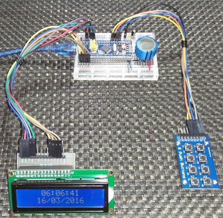
Checkout the photos and videos of the embedded RTC. The firsts are with battery backup and the latter are with supercap backup.

Project video link: https://www.youtube.com/watch?v=b4cop0915j8.
Video link: https://www.youtube.com/watch?v=sdjNY3q1khw.
Epilogue
I am very impressed with accuracy of the embedded RTC. I kept it running for several days during which deliberate power interruptions were carried out several times. Despite these abuses, the RTC kept functioning as it should. I found it as dependable as other good RTC chips. The good part is the fact that I won’t be needing any addition RTC chips any more for those projects that need time keeping.
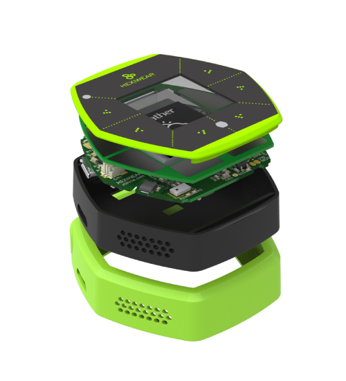
At the time of writing this article MikroElektronika launched a new product called Hexiwear. It is a hexagonally-shaped wearable IOT-based smart watch with lot of options for measurements, connectivity and expandability. It is based on an ARM chip from NXP. Because it is based on ARM, it opened a lot of possibilities for developers. If you checkout the dedicated page for Hexiwear – http://www.hexiwear.com/, you will notice that the stuffs onboard this device are mentioned on its specs but no RTC chip is mentioned and that’s because the NXP MCU just like the STM32 in this post has an embedded real-time clock unit. This product is enough to show the advantage of having an embedded RTC. In my professional career I have seen other ARM based products especially from STMicroelectronics that did not use any RTC chip rather than the embedded RTC.
References:
- STM32F10x Reference Manual
http://www.st.com/web/en/resource/technical/document/reference_manual/CD00171190.pdf - Clock or calendar implementation on the STM32F10xxx microcontroller RTC
http://www.st.com/web/en/resource/technical/document/application_note/CD00207941.pdf - Hexiwear Page
http://www.hexiwear.com/
Happy coding.
Repository: https://github.com/sshahryiar/STM32-Tutorials
Author: Shawon M. Shahryiar
https://www.youtube.com/c/sshahryiar
18.03.2016
|
|
this is a great idea!
i like post!
so i have a question: batteries vs supercaps, which is better? long time to use? and long life to use?
tks for reading, have a great, nice job!
In terms of cycle-life, simplicity, size and charging algorithm supercaps are better than batteries…. They are good for short duration power downs…. I checked that even after 1 hour of power down, a supercap as in this work can retain RTC time…. However batteries are better when cost and long duration power downs, say 2-3 weeks of power down, becomes issues….
OK since u mentioned it I would like u to work on lin peripheral, can, USB, sdio, I2c, i2s, lin for now thank you
Hi Shawon,
thank you for great text and program. ST does’t provede such comprehensive description of calendar.
I have notice for calculation day of leap year (function set_RTC and getRTC).
Day of leap year is 29. February so we can not add 86400 before end of February.
We can add one day 86400 (day of leap year) on end of February so I would like extend condition from
if (check_for_leap_year(cal_year) == 1)
to
if (check_for_leap_year(year) == 1 && month > 1) // 1 – because step before decrementing month
Regards and thank you,
Lukas
once again thank you very much on this tutorial but i would also like you to do tutorials on dma (direct memory access) and some other modules in the stm32 thank you
You are welcome….
I’m working on STM32 DMA but also waiting for MikroE to release DMA libraries as they pledged so…. Currently I’m writing a tutorial on short range communications like SPI, I2C and one-wire…. It’ll come next but can’t tell you the ETA….
Could you suggest what else do you want to see more in this tutorial series?
Hi,
Thank you for the posts. However I have an issue…
I use uVision5 and the program does not recognize most of the functions for example: set_backup_domain_software_reset(true);
is a library needed?
please help
This code was not written for Keil…. It was written for MikroC for ARM compiler….