Tag Archives: mikroC


Lab 20: Interfacing a KS0108 based Graphics LCD (Part 1)

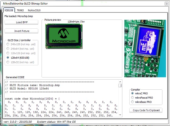
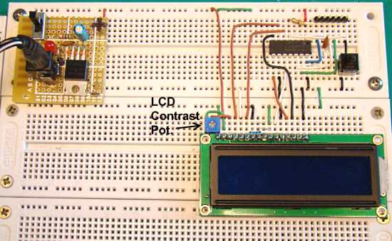
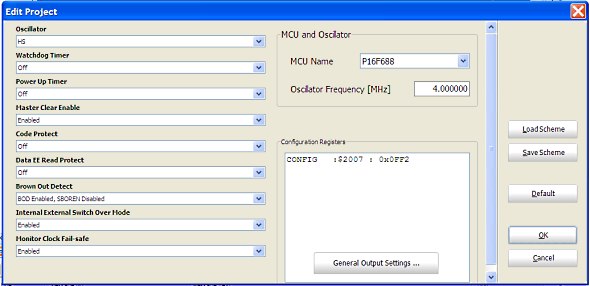
The use of a graphical LCD (GLCD) drastically changes the look of your project. It provides more freedom for presenting data than the HD44870 based character LCDs. Today we will see how to interface a KS0108 (name of the display controller chip) based GLCD to a PIC microcontroller. This experimental tutorial is divided into two parts. In the first part, we will see how to write a firmware for the PIC microcontroller to initialize the GLCD and send data to plot points and lines on the screen. The second part will focus more on exploring the built-in GLCD Library of mikroC Pro for PIC compiler to display more complex texts and objects. Since GLCDs are real resource hungry devices (in terms of required I/O pins and memory), a bigger size PIC microcontroller (PIC16F887, which has 36 I/O pins and 14KB flash memory) is selected for this experiment. I am using MikroElektronika’s UNI-DS6 development board to demonstrate this project, but the circuit setup can also be made on a breadboard.

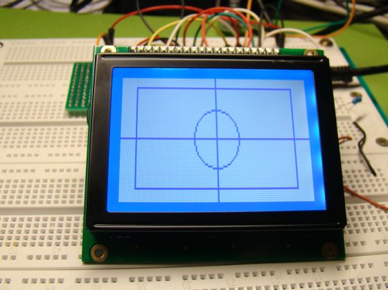
Interfacing a 128x64 pixels GLCD

Read more

Lab 19: Play musical notes

We have discussed in the past experiments how to use a PIC microcontroller to do a variety of things from flashing an LED to driving a motor, etc. Today, we will see how to play notes of a song with a PIC microcontroller. Musical notes are simply sound waves of particular frequencies. If the frequency of a note is known correctly, a microcontroller can be programmed to play the note by generating a square wave (of the same frequency) signal at one of its I/O pins. The signal must be fed to a speaker to listen to the sound. Here, we will discuss playing notes of the popular “Happy birthday to you” tune using a PIC16F628A microcontroller and a buzzer.

Musical notes using a PIC micro

Read more

How to use mikroElektronika’s GLCD bitmap editor tool to convert a BMP image in to a data array

This tutorial describes how to use the mikroElektronika’s GLCD bitmap editor tool to convert a monochromatic bit map (BMP) image file into a data array so that it could be displayed on a graphics LCD using a microcontroller. The GLCD bitmap editor tool is embedded into mikroElektronika’s compilers. It can generate a code equivalent of a BMP image, which can be easily inserted into the microcontroller’s source program.

MikroElektronika's GLCD BMP editor

Read more

Lab 4: Interfacing a character LCD

Description

HD44780 based LCD displays are very popular among hobbyists because they are cheap and they can display characters. Besides they are very easy to interface with microcontrollers and most of the present day high-level compilers have in-built library routines for them. Today, we will see how to interface an HD44780 based character LCD to a PIC16F688 microcontroller. The interface requires 6 I/O lines of the PIC16F688 microcontroller: 4 data lines and 2 control lines. A blinking test message, “Welcome to Embedded-Lab.com”, will be displayed on the LCD screen.

Required Theory

All HD44780 based character LCD displays are connected through 14 pins: 8 data pins (D0-D7), 3 control pins (RS, E, R/W), and three power lines (Vdd, Vss, Vee). Some LCDs have LED backlight feature that helps to read the data on the display during low illumination conditions. So they have two additional connections (LED+ and LED-), making altogether 16 pin. A 16-pin LCD module with its pin diagraam is shown below.

Read more

Lab 1: Flashing an LED

Description

Today is our first session in PIC microcontroller lab, and we will begin with an experiment that flashes an LED on and off. While this looks very simple it is the best project to start because this makes sure that we successfully wrote the program, compiled it, loaded inside the PIC, and the circuit is correctly built on the breadboard.

In this lab session we will connect an LED to one of the port pin of PIC16F688 and flash it continuously with 1 sec duration.

Required Theory

You must be  familiarized with,

  • digital I/O ports (PORTA and PORTC) of PIC16F688
  • direction control registers, TRISA and TRISC
  • special function registers CMCON0 and ANSEL

If you are not then please read this first: Digital I/O Ports in PIC16F688.

Circuit Diagram

To our basic setup on the breadboard (read Getting Ready for the First Lab), we will add a light-emitting-diode (LED) to port pin RC0 (10) with a current limiting resistor (470 Ohm) in series. The complete circuit diagram is shown below.

Read more

« Older Entries Recent Entries »