Tag Archives: PIC16F688


MikroC Pro for PIC : Installation and Setup

My PIC tutorials and projects use MikroC compiler for firmware development. But I don’t think I ever posted anything on its installation and setup. Today, I am going to show how to install MikroC Pro for PIC (v4.60) on a Windows PC. First of all, download the zipped installation file from here, unzip it and run the setup program. Installation is straightforward. When you first start the MikroC compiler, it opens a LED blinking example project. You can close this project by clicking on ‘Close Project’ under Project menu. Read more

Lab 10: DC motor interfacing to PICMicro

Description

Perhaps one of the most entertaining things to do with an embedded microcontroller is to get it to actually move something. Three very popular devices used to “make things move” include dc motors, RC servos, and stepper motors. This lab session will look at how you can interface a dc motor to a PIC microcontroller.

Required Theory

DC motors are simple two-lead, electrically controlled devices that convert electrical power into mechanical power through the interaction of two magnetic fields. One field is usually produced by a stationary permanent magnet (on the stator), and the other field is produced by an electric current flowing in the motor coil (on the rotor). The interaction of the two fields results in a torque that tends to rotate the rotor. For this experiment, a reversible, permanent magnet, brushed DC motor is selected. The term ‘reversible’ means the rotation of the motor can be reversed by simply flipping the terminals of the DC power supply. One such motor is shown below. I got it from my old broken printer. The dc motors are found in CD players, toy cars, cassette player, printers, etc.

Read more

Running message display project for Christmas

Introduction

As Christmas is coming people have already lightened their houses. I thought of doing something different for this Christmas besides the festive Christmas lights. I made a running message display using LEDs, and thought of sharing it with you. This is a very simple running message display project that displays the message ‘MERRY XMAS’, where each letter is created with 5mm diameter red-color LEDs. The 9 letters in the message are individually turned on or off through a PIC16F688 microcontroller’s I/O pins. Therefore, a variety of display patterns can be generated through the software inside the microcontroller.

Christmas running message display

Read more

Lab 7: PIC Timers and Counters (Part 1)

Description

PIC microcontrollers are equipped with one or more precision timing systems known as Timers. They can be used to perform a variety of time precision functions, such as generating events at specific times, measuring the duration of an event, keeping date and time record, counting events, etc. The main component of a timer module is a free running binary counter that increments for each incoming pulse. Since it runs independently, it can count pulses concurrently with the main program execution. A PIC16F688 microcontroller has two built-in hardware timer modules: Timer0 and Timer1. Today’s lab lesson will explore the functionality of the Timer0 module.

Required Theory

The fundamental concept of a timer/counter module is discussed in Timers and Counters. It is simply an independent binary counter that can be configured to count instruction cycles or to count external clock pulses. The Timer0 module in a PIC16F688 microcontroller is an 8-bit synchronous counter that stores the value for the counter in the special function register called TMR0. This register can be read or written at any time by software. If you write a value to it, the counter will start incrementing from there.
Read more

Lab 5: Analog-to-digital conversion (ADC)

Description

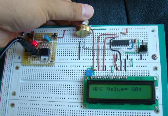
Analog-to-digital conversion (ADC) is necessary because, while embedded systems deal with digital values, their surroundings typically involve many analog signals such as, temperature, speed, pressure, the output of a microphone, etc. They all need to be converted into digital data before being processed by the microcontroller. Today, we will see how to read an external analog signal using a PIC16F688 microcontroller, and display the conversion output (a digital number) on a LCD. The input analog signal will be a varying voltage between 0-5V derived using a potentiometer.

Required Theory

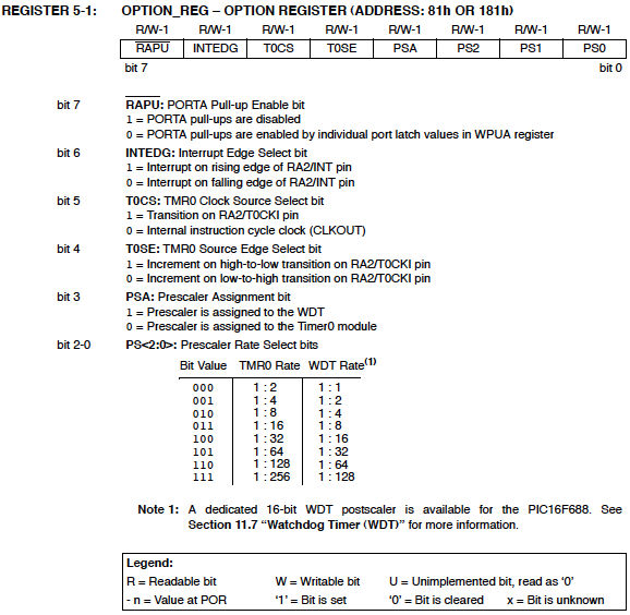
The PIC16F688 microcontroller has a built-in 10-bit ADC with eight input channels. The eight channels are available at RA0, RA1, RA2, RA4, RC0, RC1, RC2, and RC3. They have alternate labels, AN0-AN7, for this function, and are multiplexed into a single Sample and Hold circuit. The output of the Sample and Hold is connected to the input of the A/D converter. The 10-bit conversion result is stored  into the ADC result registers ADRESH (A/D Result Higher byte) and ADRESL (A/D Result Lower byte). Each of these registers is 8-bit. The functionality of the A/D module is controlled by three registers: ANSEL, ADCON0, and ADCON1. The details of these control registers are discussed in ADC channels in PIC16F688.
Read more

« Older Entries Recent Entries »