Tag Archives: PIC16F688


Lab 3: Four bit binary counter

Description

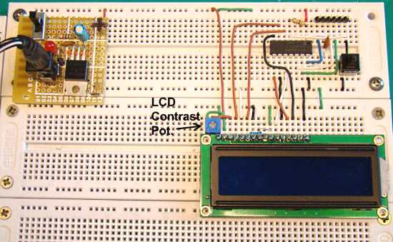
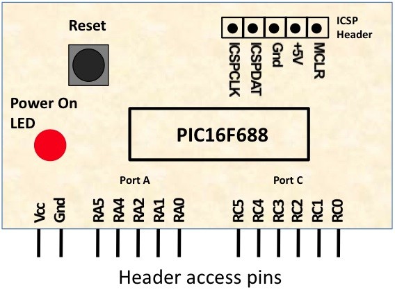
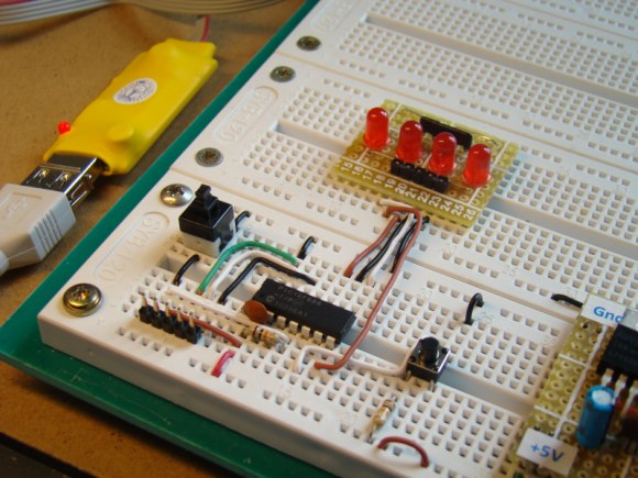
Today’s lab session is about binary counting LEDs. The binary 1 and 0 will be represented by turning LEDs on and off. You will make a 4-bit binary counter (using 4 LEDs) that counts from 0 to 15 (0000-1111 binary). The four LEDs are connected to RC0 through RC3 port pins of PIC16F688 with current limiting resistors (470? each) in series. A push button switch is connected to pin RC4 to provide input for the counter. The counter starts from 0, and increase by 1 every time the button is pressed. When the counter reaches 15 (all LEDs on), it will reset to 0 on the next press of the button.

Required Theory

You should be familiar with the digital I/O ports of PIC16F688 and their direction settings. If you are not, read Digital I/O Ports in PIC16F688. Read previous lab session (Lab 2: Basic digital input and output) to learn about reading inputs from a push button.
Read more

Lab 4: Interfacing a character LCD

Description

HD44780 based LCD displays are very popular among hobbyists because they are cheap and they can display characters. Besides they are very easy to interface with microcontrollers and most of the present day high-level compilers have in-built library routines for them. Today, we will see how to interface an HD44780 based character LCD to a PIC16F688 microcontroller. The interface requires 6 I/O lines of the PIC16F688 microcontroller: 4 data lines and 2 control lines. A blinking test message, “Welcome to Embedded-Lab.com”, will be displayed on the LCD screen.

Required Theory

All HD44780 based character LCD displays are connected through 14 pins: 8 data pins (D0-D7), 3 control pins (RS, E, R/W), and three power lines (Vdd, Vss, Vee). Some LCDs have LED backlight feature that helps to read the data on the display during low illumination conditions. So they have two additional connections (LED+ and LED-), making altogether 16 pin. A 16-pin LCD module with its pin diagraam is shown below.

Read more

PIC16F688 breadboard module for quick prototyping

This module is based upon the basic setup circuit for PIC16F688 that I have described in one of my PIC lessons, Getting ready for the first lab. I thought of soldering this circuit on a general purpose ptototyping board and use male headers to access the power supply pins and I/O ports of the PIC16F688 microcontroller. This will free up a lot of space on the breadboard as the ICSP header and the reset switch are transferred from the breadboard to the module. This will make prototyping on the breadboard easier and quicker. The general layout of the module is shown below. It is followed by the circuit diagram.

Read more

ADC channels in PIC16F688

The PIC16F688 microcontroller has a built-in 10-bit ADC with eight input channels. The eight channels are available at RA0, RA1, RA2, RA4, RC0, RC1, RC2, and RC3. They have alternate labels, AN0-AN7, for this function, and are multiplexed into a single sample and Hold circuit. The output of the sample and hold is connected to the input of the A/D converter. The A/D conversion is successive approximation based and the 10-bit result is stored  into the ADC result registers ADRESH (A/D Result Higher byte) and ADRESL (A/D Result Lower byte). Each of these registers is 8-bit.

Pin diagram of the PIC16F688 microcontroller

Read more

Lab 1: Flashing an LED

Description

Today is our first session in PIC microcontroller lab, and we will begin with an experiment that flashes an LED on and off. While this looks very simple it is the best project to start because this makes sure that we successfully wrote the program, compiled it, loaded inside the PIC, and the circuit is correctly built on the breadboard.

In this lab session we will connect an LED to one of the port pin of PIC16F688 and flash it continuously with 1 sec duration.

Required Theory

You must be  familiarized with,

  • digital I/O ports (PORTA and PORTC) of PIC16F688
  • direction control registers, TRISA and TRISC
  • special function registers CMCON0 and ANSEL

If you are not then please read this first: Digital I/O Ports in PIC16F688.

Circuit Diagram

To our basic setup on the breadboard (read Getting Ready for the First Lab), we will add a light-emitting-diode (LED) to port pin RC0 (10) with a current limiting resistor (470 Ohm) in series. The complete circuit diagram is shown below.

Read more

« Older Entries Recent Entries »