Tag Archives: PIC16F688


Digital I/O Ports in PIC16F688

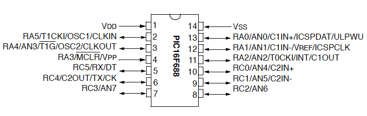
PIC16F688 is a 14-pin flash-based, 8-bit microcontroller. It can be obtained in different packages, but the DIP (Dual In-line Package) version is recommended for prototyping. The figure below shows a PIC16F688 microcontroller in DIP chip, and its pin outs.

Most of the pins are for input and output, and are arranged as PORTA (6) and PORTC (6), giving a total of 12 I/O pins.  All of these can operate as simple digital I/O pins but they do have more than one function. For example, eight of total 12 I/O pins also serve as analogue inputs for the internal analog-to-digital converter (ADC). Similarly, the PORTA pins RA0 and RA1 are also used to serially load an user program into the PIC16F688 flash memory. The mode of operation of each pin is selected by initializing various control registers inside the chip. All these options will be discussed later on.
Read more

Hardware and Software requirements

The development of an embedded system requires some hardware and software products. Although the hardware requirements depend on the type and complexity of the project, the following hardware tools are required in all of the experiments we are going to discuss here.

  1. A solderless breadboard for constructing and testing the experimental circuits. The breadboard is chosen because it is reusable. You can change, modify or remove the components on it at any time. While an embedded system is in development phase, you never know in advance whether or not your circuit will function correctly when assembled. So it is always good to test it first on a breadboard. Once it performs well, the circuit can be transferred to a printed circuit board.
  2. Microcontroller chips (PIC16F688 and PIC16F628A in this case)
  3. A PIC programmer to load firmware inside the microcontroller. You need to buy one with in circuit serial programming(ICSP) capability. This allows you to quickly program the PIC while it is in the target circuit. I have got an iCP01 USB PIC programmer from iCircuit Technologies. It is very handy, easy to use, and low-cost ICSP programmer for the most popular flash-based PIC microcontrollers. The best thing about it is that it is compatible with Microchip’s PICKit2 and MPLAB IDE softwares. And, it works great. Read Choosing a PIC Programmer.
  4. A PC is required for two purposes: to develop and compile the firmware for the microcontroller, and to transfer it to the PIC programmer so that it could be loaded into the program memory of the microconroller.
  5. A regulated +5V DC source to power your circuit on the breadboard.
  6. A digital multimeter as test equipment.
  7. Other components like resistors, LEDs, capacitors, wires, etc as required.

iCP01 USB PIC programmer that uses PICkit2 software for programming

Required Software Tools

In addition to the above hardware, following software products are required during the experiments.

  1. A Compiler to develop and compile the firmware. You need to download and install the free version of mikroC Pro for PIC (a C compiler for PIC from Mikroelektronika) to follow these experiments. Here is the download link: mikroC Pro for PIC. Also download mikroC Pro manual and Create First Project. These user’s manuals describe the compiler features and setup procedure in detail.
  2. A microcontroller device programmer software that’s provided by the vendor along with the programmer hardware. It is required to transfer the firmware from the PC to the microcontroller. You can download PICkit2 programming software for iCP01 USB PIC programmer here.

Lab 2: Basic digital input and output

Description

Today we will learn how to read digital inputs from a push button switch. A digital input has only two values: 1 and 0. The configuration of the push button switch is same as that of the reset switch except it goes to a different port pin. The status of the switch will be read through RC1 and every time when it is pressed, an LED connected to RC0 will be toggled ON and OFF.

Required Theory

You must be familiar with the digital I/O ports of PIC16F688 and their direction settings. If you are not, read Digital I/O Ports in PIC16F688.

Circuit Diagram

To our last setup (see Lab 1: Flashing an LED), connect a push button switch to RC1 as shown below. The input ports of a PIC microcontroller have very high input impedance, and therefore, during normal condition when the switch is open, the RC1 pin is pulled ‘High’ through the external 10K resistor. When the switch is pressed, RC1 is pulled to ground and the microcontroller will read it as logic ‘Low’. In this way, a simple push button switch with a pull-up resistor can be used to provide digital inputs (1 and 0) to the microcontroller. Read more

Getting ready for the first lab

This is to be followed after you have successfully completed the following steps:

Basic setup on the breadboard

As mentioned before all the experimental circuits will be constructed on the breadboard because it is easy to modify the circuit and correct any wiring error. Figure 1 shows the pin diagrams of PIC16F688. It is a 14-pin microcontroller with a precision internal oscillator. It provides 12 I/O pins with individual direction control, and can drive LEDs directly. 8 out of 12 I/O pins also serve as ADC channels for the internal 10-bit ADC. The various features of PIC16F688 will be discussed later in more detail in following lab sessions. For now, we will look at a simple circuit setup for PIC16F688 on the breadboard that will be used in all the experiments.

Read more

PIC based shaking LED dice

Electronics dice projects using push buttons are available all over the internet. This one is a little bit different. It is meant to provide the real feeling of shaking a dice by using a spring with weight and a wire. The two make and break contacts when shaken. The PIC16F688 microcontroller detects the contacts between the spring and the wire, and rolls the dice. After the spring motion stopped completely, the dice output number is displayed with glowing LEDs.

Read more

Recent Entries »