Lab 1: Flashing an LED
|
|
Description
Today is our first session in PIC microcontroller lab, and we will begin with an experiment that flashes an LED on and off. While this looks very simple it is the best project to start because this makes sure that we successfully wrote the program, compiled it, loaded inside the PIC, and the circuit is correctly built on the breadboard.
In this lab session we will connect an LED to one of the port pin of PIC16F688 and flash it continuously with 1 sec duration.
Required Theory
You must be familiarized with,
- digital I/O ports (PORTA and PORTC) of PIC16F688
- direction control registers, TRISA and TRISC
- special function registers CMCON0 and ANSEL
If you are not then please read this first: Digital I/O Ports in PIC16F688.
Circuit Diagram
To our basic setup on the breadboard (read Getting Ready for the First Lab), we will add a light-emitting-diode (LED) to port pin RC0 (10) with a current limiting resistor (470 Ohm) in series. The complete circuit diagram is shown below.

Flashing LED circuit

Prototyped circuit on the breadboard
Software
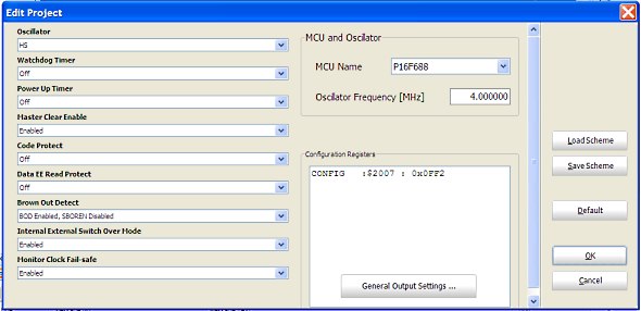
Open a new project window in mikroC and select Device Name as PIC16F688. Next assign 4.0 MHz to Device Clock. Go to next and provide the project name and the path of the folder. It is always a good practice to have a separate folder for each project. Create a folder named Lab1 and save the project inside it with a name (say, FlashLED). The mikroC project file has .mccpi extension. The next window is for “Add File to Project “. Leave it blank (there are no files to add to this project) and click next. The next step is to include libraries, select Include All option. Next, click Finish button. You will see a program window with a void main() function already included. Now, go to Project -> Edit Project. You will see the following window.

This window allows you to program the configuration bits for the 14-bit CONFIG register inside the PIC16F688 microcontroller. The device configuration bits allow each user to customize certain aspects of the device (like reset and oscillator configurations) to the needs of the application. When the device powers up, the state of these bits determines the modes that the device uses. Therefore, we also need to program the configuration bits as per our experimental setup. Select,
Oscillator -> Internal RC No Clock
Watchdog Timer -> Off
Power Up Timer -> On
Master Clear Enable -> Enabled
Code Protect -> Off
Data EE Read Protect -> Off
Brown Out Detect -> BOD Enabled, SBOREN Disabled
Internal External Switch Over Mode -> Enabled
Monitor Clock Fail-Safe -> Enabled
Note that we have turned ON the Power-Up Timer. It provides an additional delay of 72 ms to the start of the program execution so that the external power supply will get enough time to be stable. It avoids the need to reset the MCU manually at start up.
Read PIC16F688 datasheet for details on Configuration Word.

Appropriate configuration bit selection
Here’s the complete program that must be compiled and loaded into PIC16F688 for flashing the LED. Copy and paste this whole program in your main program window. You have to delete the void main() function first that was already included. To compile, hit the build button, and if there were no errors, the output HEX file will be generated in the same folder where the project file is. Then load the HEX file into the PIC16F688 microcontroller using your programmer.
Output
You will see the LED flashing On and Off with 1 sec duration.

|
|
What is the In circuit debugger that you all used. I have a ICD3 but i cant do it.
Thanks.
I Want Code for 4 led contiously On in micro C without delay
Sir,
Delay_ms(1000); this function creates a delay of 1000 ms or 1 second, so Delay_ms(600000); will it creare 10 minute delay in micro C with 16f688 micro or how should we create 10 minute delay in micro C
[10 minutes = 10X60 sec = 10x60x1000ms]
Regards,
Akash
R-B
I tried to Flash a LED connected in RB0 (Pin 6) of PIC 16F628A and write following program in Micro C (getting idea from your example with PIC 16f688 LED Flashing)
sbit LED at RB0_bit;
void main()
{
CMCON = 0x07; //disable comparator
TRISA= 0b00001000;
TRISB =0b00000000;// PORTB all output
do
{
LED = 1;
Delay_ms(1000);
LED= 0;
Delay_ms(1000);
}
while (1); // infinite loop
}
Compilation done successfully and .HEX file downloaded but found LED glows contentiously , not flashing,
I kept MCLR disable and 4 MHZ internal oscillator selection from MICRO C project editor and used “IC-Prog” (1.05D)- to download the .HEX file .
Can you please help me , where I am doing wrong .
Regards,
Uttam
NB:-can you provide attachment option with comment field
sbit LED at RB0_bit;
void main() {
CMCON = 0*07 ; // Disbale comparators
TRISB = 0b00000000; // PORTC All Outputs
do {
LED = 1;
Delay_ms(1000);
LED = 0;
Delay_ms(1000);
} while(1); // Infinite Loop
}
At first you take a micro love from mynano heart.I want to get all PIC 12F to 18F practice project sheet or as begging level.Is is possible & how way ?
Please solve my problem, i trying when button push after led.1 on and with sound play. and another led and sound same operation.program used mikro c
I just downloaded MikroC and there isn’t a PIC16F688 device in the dropdown list. Is it a deprecated device or is there another one that is compatible?
There must be PIC16F688 device in the list. Check it again.
if I want to download the source to a pic16f628a what should parameters should I change?
What are your hardware settings for PIC16F628A? I mean the clock source and the MCLR pin. Then you set the configuration bits accordingly. After that,
sbit LED at RB0_bit;
void main() {
CMCON = 0×07 ; // Disbale comparators
TRISB = 0b00000000; // PORTC All Outputs
do {
LED = 1;
Delay_ms(1000);
LED = 0;
Delay_ms(1000);
} while(1); // Infinite Loop
}
Hi pal,
I understand it now. Thanks a lot.
Hi sir,
You are using internal osc 4Mhz with delay_ms(1000) and
the led blinks On and Off with 1 sec duration.
I have two questions:
One: If I use another pic with the internal osc 8MHz with the same delay
will the led blink on and off with 1/2 sec duration?
Two: How come with the internal osc 4Mhz, the led blinks on and off
with 1 sec duration?
Would you kindly show me how to calculate this?
Thanks so much.
@simon,
The compiler creates a software delay of 1 sec if you use delay_ms(1000). Delay_ms() is the library routine provided in mikroC Pro for PIC. It uses the selected clock frequency to determine the delay routine. So, if you select 8.o MHz internal clock in your configuration word (Project -> Edit Project window), then delay_ms(1000) will still create 1 sec delay, as the compiler generates a different delay routine based on the new clock setting. Delay_ms provides delay in millisecond. So 1000 ms is 1 sec.
I started with my first project but it didn’t worked so i decided to go back and blink leds,now the problem is when the delay between on off was set 10ms the leds took 2.3sec(used a stopwatch n delay was approx. 2.3sec).
At first delay was set to 500ms but it took too much time to blink so delay was set to 10ms.
CCS compiler demo version was used for compiling , 4MHz crystal oscillator was used with 22pF capacitors and configuration bits 2F09 were entered in PICKIT 2 v2.61 (not used in the code)
#include
#use delay(clock=4000000)
void main()
{
while(1)
{
output_D(255);
delay_ms(10);
output_D(0);
delay_ms(10);
}
}
please solve my problem and tell me the changes to be made in program to make it run with correct delay time.
someone told me that it might be because of the prescaler,
prescaler works on timers i think and here no timer was used.
Sorry, my programs are written in MikroC Pro for PIC compiler. I haven’t used CCS so far.
great project for beginner. I used to play with this kind of project about 10years ago..hello world
While doing copy and paste, some characters and symbols go wrong in MikroC editor. Make sure everything looks the same on the editor as in the program given above. I think I should also provide the source code file to download along with the HEX file, so there won’t be any problem.
Hello
i copy paste the program in MicroC then i compiled it and i get errors like this:
‘;’ expected but LED found
i don’t know what is the problem
Hello
i copy paste the program in MicroC then i compiled it and i get errors like this:
‘;’ expected but LED found
OK, now I understand.
Thank you
Kevin,
CMCON0=7 and CMCON0=0x07 are same. Now I understood what the problem was. While you copied and paste the code, the ‘x’ sign is just messed up. It had happened to me too. 0x07 is the way to write numbers in hexadecimal. So, instead of copying and pasting the line CMCON0=0x07, if you type it, it will work. I had that experience before.
Hello again
I have found out what the problem was
The command CMCOCN0=0x07;
should read
CMCOCN0=7;
I assume this is a change in the version of compiler (4.60) from the version you used when you wrote the project files.
After I corrected this, the project compiled.
Have not fully tested it yet, but thought you should know what I found out and I hope I’m correct with my answer.
Thank you
Sorry that was a typo error on my part.
I originally copied and paste the code from the Lab 1 webpage into MikroC and then ran the build project option. I wanted to understand more about using MikroC, rather than just loading the HEX file direct into the MCU.
I get the following error messages
Line Message No. Mesage text
11 402 ; expected, but ‘×’ found lab 1.c
11 424 ‘}’ expected ‘;’ found lab 1.c
21 371 Specifier needed lab 1.c
21 396 Invalid declarator expected'(‘ or identifier lab 1.c
21 371 Specifier needed lab 1.c
21 300 Syntax Error: ‘)’ expected, but ‘1’ found lab 1.c
22 371 Specifier needed lab 1.c
22 396 Invalid declarator expected'(‘ or identifier lab 1.c
22 402 ; expected, but ‘}’ found lab 1.c
22 312 Internal error ” lab 1.c
0 102 Finished (with errors): 23 Dec 2010, 18:56:49 lab 1.mcppi
I have contacted Mikroelectronica just in case it is something to do with the version of the compiler.
Any help/advise would be useful.
Thanks
It should be CMCON0=0x07;
The last letter in CMCON0 is zero, and not alphabet O.
Hello,
I have followed the steps to creating this lab project but when I try to compile the code, I get a number of errors.
The first one being ;expected, but ‘x’found on the line
CMCONO – 0x07 ; //Disable comparators
I’m using the latest version of MikroC 4.60 and include all libaries when I run through the project wizard.
Any ideas ?
Thanks