0-9999 seconds count down timer using PIC12F683 microcontroller

|
|
The goal of this project is to construct a simple 0-9999 seconds count down timer with an alarm and a display. The time is set through two tact switches and the count down seconds are displayed on a 4-digit seven segment LED display. The project uses PIC12F683 microcontroller for all I/O and timing operations and MAX7219 IC for driving the seven segment LED module. The time out condition is indicated by an audible alarm from a buzzer.
Circuit diagram
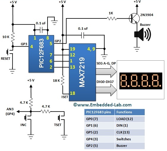
The complete circuit diagram of this project is shown below. Two tact switches (named INC and TSET) are used for setting time and turning the timer on. These switches are connected in parallel and their inputs are read through the AN3 ADC channel of PIC12F683 microcontroller. You can see from the circuit diagram how these two tact switches give rise to different analog voltages when pressed. When INC is pressed, the input voltage to AN3 pin is 0. But if TSET is pressed, the input to AN3 ADC channel would be around 2.5V (two 4.7K resistors make a voltage divider network). And if none of them are pressed the ADC input is pulled up close to 5V. Therefore, based on the value of 10-bit ADC count, it is possible to detect and identify if any of the two switches is pressed. The buzzer is driven by a PWM signal generated at the GP2 output pin of PIC12F683. The display part uses a 4-digit seven segment (common cathode type) LED module which is driven by the MAX7219 IC. If you are not familiar with MAX7219 device, please read my earlier project Serial four digit 7-segment LED display module for further detail on that.
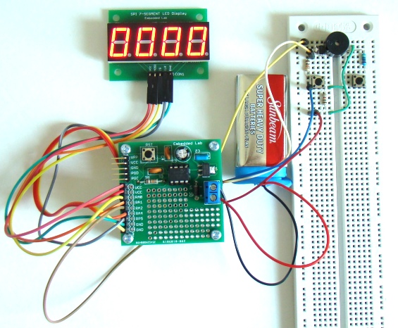
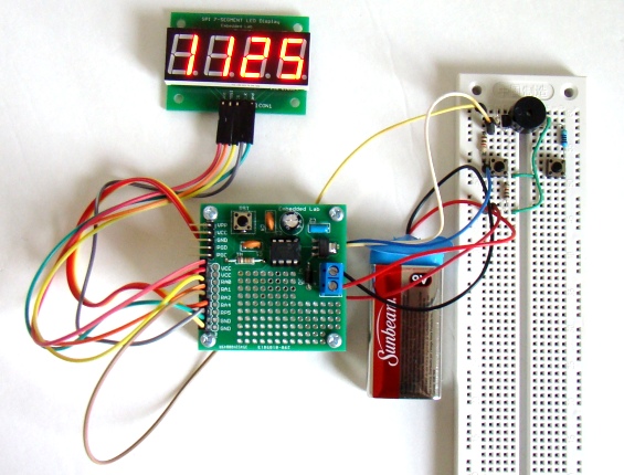
The picture below shows the complete setup of the project. I am using my PIC12F project board and MAX7219 based seven segment LED display module for illustration. The buzzer and tact switches are wired on a breadboard but they can easily fit over the small prototyping area available on the PIC12F project board.
Software
The firmware is developed in C and compiled with mikroC Pro for PIC compiler. The driver routine for MAX7219 is taken from my previous project Serial four digit 7-segment LED display module. A 5KHz PWM signal is generated at the CCP1 output pin for the audible alarm when the timer is out. The overall operation of this timer project is described in the next section. That will help you to understand how the firmware for this project works. Here’s the complete source code for this project. A download link for source and HEX files is also provided below.
// Define Software-SPI connections for MAX7219 #define CS_Pin GP0_bit #define MOSI_Pin GP1_bit #define CLK_Pin GP5_bit unsigned short i, k, unit=0, ten=0; unsigned int counter = 0, hundred=0, thousand=0, l; void SPI_Write_Byte(unsigned short num){ unsigned short t, Mask, Flag; CLK_Pin = 0; Mask = 128; for (t=0; t<8; t++){ Flag = num & Mask; if(Flag == 0) MOSI_Pin = 0; else MOSI_Pin = 1; CLK_Pin = 1; CLK_Pin = 0; Mask = Mask >> 1; } } void MAX7219_INIT() { // Disable Shutdown mode CS_Pin = 0; // CS pin is pulled LOW SPI_Write_Byte(0x0C); // Select Shutdown register SPI_Write_Byte(0x01); // Set D0 bit to return to normal operation CS_Pin = 1; // CS pin is pulled HIGH // Set BCD decode mode for digits DIG0-DIG3 CS_Pin = 0; // CS pin is pulled LOW SPI_Write_Byte(0x09); // Select Decode Mode register SPI_Write_Byte(0x0F); // Select BCD mode for digits DIG0-DIG3 CS_Pin = 1; // CS pin is pulled HIGH // Set display brighness CS_Pin = 0; // CS pin is pulled LOW SPI_Write_Byte(0x0A); // Select Intensity register SPI_Write_Byte(0x0F); // Set maximum brightness CS_Pin = 1; // CS pin is pulled HIGH // Set display refresh CS_Pin = 0; // CS pin is pulled LOW SPI_Write_Byte(0x0B); // Select Scan-Limit register SPI_Write_Byte(0x03); // Select digits DIG0-DIG3 CS_Pin = 1; // CS pin is pulled HIGH // Enable Display-Test CS_Pin = 0; // CS pin is pulled LOW SPI_Write_Byte(0x0F); // Select Display-Test register SPI_Write_Byte(0x01); // Enable Display-Test CS_Pin = 1; // CS pin is pulled HIGH Delay_ms(1000); // Disable Display-Test CS_Pin = 0; // CS pin is pulled LOW SPI_Write_Byte(0x0F); // Select Display-Test register SPI_Write_Byte(0x00); // Disable Display-Test CS_Pin = 1; // CS pin is pulled HIGH } void Display_Counter(unsigned int j){ CS_Pin = 0; // CS pin is pulled LOW SPI_Write_Byte(4); // Send thousands digit SPI_Write_Byte((j/1000)%10); CS_Pin = 1; // CS pin is pulled HIGH CS_Pin = 0; // CS pin is pulled LOW SPI_Write_Byte(3); // Send hundreds digit SPI_Write_Byte((j/100)%10); CS_Pin = 1; // CS pin is pulled HIGH CS_Pin = 0; // CS pin is pulled LOW SPI_Write_Byte(2); // Send tens digit SPI_Write_Byte((j/10)%10); CS_Pin = 1; // CS pin is pulled HIGH CS_Pin = 0; // CS pin is pulled LOW SPI_Write_Byte(1); // Send ones digit SPI_Write_Byte(j%10); CS_Pin = 1; // CS pin is pulled HIGH } void update_counter(){ counter = thousand*1000 + hundred*100 + ten*10 + unit; } void digit_refresh(unsigned short n){ // Set display refresh CS_Pin = 0; // CS pin is pulled LOW SPI_Write_Byte(0x0B); // Select Scan-Limit register SPI_Write_Byte(n); // Select digits DIG0-DIG3 CS_Pin = 1; // CS pin is pulled HIGH } void delay_debounce(){ Delay_ms(300); } void blink_zeros(){ unsigned short loop; for (loop = 0; loop < 5; loop++) { // Enable Shutdown mode CS_Pin = 0; // CS pin is pulled LOW SPI_Write_Byte(0x0C); // Select Shutdown register SPI_Write_Byte(0x00); // Set D0 bit to return to normal operation CS_Pin = 1; // CS pin is pulled HIGH delay_debounce(); digit_refresh(3); // Disable Shutdown mode CS_Pin = 0; // CS pin is pulled LOW SPI_Write_Byte(0x0C); // Select Shutdown register SPI_Write_Byte(0x01); // Set D0 bit to return to normal operation CS_Pin = 1; // CS pin is pulled HIGH delay_debounce(); } } unsigned short time_set_mode = 0, select_digit, TMRON = 0; void main() { TRISIO=0b00011000; // GP3, GP4 are input GPIO=0x00; // All O/Ps zero CMCON0 = 0x07; ANSEL = 0x08; // AN3 active MAX7219_INIT(); // initialize max7219 Display_Counter(counter); i = 0; PWM1_Init(5000); // PWM module initialization (5KHz) PWM1_Set_Duty(127); do{ if(ADC_Read(3) > 400 && ADC_Read(3) < 700 && TMRON == 0){ l = 1000; while(ADC_Read(3) > 400 && ADC_Read(3) < 700){ delay_ms(1); l--; if(l == 0 && counter > 0){ TMRON = 1; PWM1_Start(); Delay_ms(500); PWM1_Stop(); time_set_mode = 0; break; } } if(!TMRON){ digit_refresh(i); select_digit = i; i ++; if (i >=4) i = 0; time_set_mode = 1; } } if(ADC_Read(3) < 100 && time_set_mode == 1){ delay_debounce(); switch(select_digit){ case 0: unit ++; if (unit > 9) unit = 0; break; case 1: ten ++; if (ten > 9) ten = 0; break; case 2: hundred ++; if (hundred > 9) hundred = 0; break; case 3: thousand ++; if (thousand > 9) thousand = 0; break; } } if(TMRON && counter > 0){ counter --; Display_Counter(counter); Delay_ms(1000); // Initialize all relevant variables after timer runs out if(counter == 0) { TMRON = 0; unit = 0; ten = 0; hundred = 0; thousand = 0; i = 0; PWM1_Start(); blink_zeros(); PWM1_Stop(); } } if(!TMRON){ update_counter(); Display_Counter(counter); } }while(1); } |
The following picture shows the configuration bit settings (4.0 MHz internal clock, MCLR, Power-Up timer, and Brown out detection are enabled) for the PIC12F683 microcontroller.
Operation
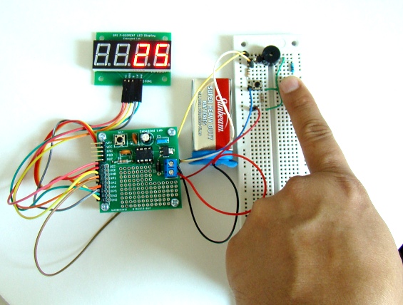
This timer operates in the following way. When the power is first turned on, the displays are initialized and you will see all four digits displaying ‘0’. In order to set time you need to select one digit at a time. You can do that by momentarily pressing TSET. At first press, it selects the units digit (rightmost digit), which by default is 0. All other digits will be blank at this point. You can use the INC switch to set the digit value anywhere between 0-9. With each pressing of INC, the digit value is incremented by 1, and it rolls over to 0 after 9. After setting the units digit value, pressing TSET selects tens digit. You can set the tens digit value in the similar way. Once all 4 digits are set, you can turn on the timer by holding the TSET button pressed for around 2 seconds. The timer starts with a short beep and you can see the left over seconds on the display. When the timer is out, the display flashes five times and an audible alarm is generated from the buzzer. The following video shows the timer in action.
Note that when the timer is running, it will not respond to any inputs given through INC and TSET switches. If you want to clear or restart the timer before it is out, you should press the Reset button.
You can buy the SPI 4-digit seven segment LED display module kit for $11.99 including shipping within the US. This allows you to interface a 4-digit 7-segment LED display with only three I/O pins of a microcontroller, and gives you full control of all digits and decimal points.
|
|


Do you have and sell a pc board for this timer?
I have boards for you hours/minutes timer and have tried to post comments to that but they have not been approved since last May. Do you have a timer similar to that but does seconds/minutes rather than minutes and hours?
Thank you.
Hi Jim,
I don’t have any timer for just seconds/minutes.
hi i,m new in stm32cube and i want to Create a seven Segment with this can you help me in this
tx a lot
Sir, pls configure the display. May you make it 99 mins and 59 seconds.thank you sir.
please how can i design “0-9999 seconds count down timer using PIC16F887 microcontroller” can you help me out
Hello R-B
Re ; my post reply,s on the 10th & 11th April last.
I was hoping that you might advise me, re’ my post, about changing the code of the 0-9999 timer project.
Many thanks
Victor
Hi Victor,
I have sent you an email with the modified HEX code. Just load it in your PIC12F683 and see how it does. The circuit should not change.
re Bleep. I am aware that by changing the code it may not be possible to have the bleeper facility within the new program.
This will not be problem, I can generate a PWM source seperate to the timer , to power the bleeper.
Many thanks again
Victor
Hello again, my gratfull thanks for your interest.
It would be my intension to intigrate the circuit into a home made Ultra Violet Exposure cabinet which at present has a timer based on a 555 ic device which does not give a consistant result.
The 0-9999 timer sequence I would like is;
Power up / set parameters (seconds)/press Run/ 500ms bleep / Start countdown / Pin 5 goes High and stays High for the completion of the countdown / at 0000 a 1000ms bleep / End of cycle.
Pin 5 GP2 output would be used to power a 12vdc relay (via a 2N3904 transistor)The relay would in turn operate the UV tubes.
I hope this helps , It would be great if it could be done.
Thank you
Victor
Hi,
Thanks for the reply. I looked on the WEB for a copy of MikroC Pro,The only one I can find costs several hundred dollars !
My idea with the Latch type relay did’nt work , so I am convinced the only way is to get the code altered so that the Pic 12F683 gives a continous output during the countdown period.
If I can’t get a modified code or HEX file , I think I will have to abandon the project.That would be a drag since I have already assembled the circuit and it works fine, and would be perfect if I could make it drive a 12v relay via a transister.
Maybe I can make a request directly to Embeded Labs to ask for their help. What do you think !
If anyone can help me out here, my Email address is
aughtoncottagecosy@live.co.uk
Thanks
Victor
Hi Victor,
Can you tell us what exactly are your requirements? Can you explain step by step what you want the timer to do for you?
Further to my last post.
Yes I am using a 2n3904 transister to switch on the relay.It will be a dpdt latch with 2 coils.
I use MPLAB IDE V8.60 in conjuction with a PICkit 2 for programming my projects, howeever when I load the ASM file into mplab , the build fails on error 113, which I understand could be a symbol , inc file or syntax fault.
I know very little about codes,and at 73years old it might be bit late for me to learn !!!!! so I need some kind person to have a look at this problem and help sort it out for me. Please …………
Victor
Hi Victor,
You should use MikroC Pro for PIC compiler to edit and compile the source code here.
Thank you for your replies and very helpfull links.
In fact they have made me consider that I have been “barking up the wrong tree”.Instead , why not consider using the first pulse to switch on a latch type relay and the second pulse to switch off the relay.
The fact that the first pulse 500ms occurs at the beginning of the timed period and the second pulse 1000ms at the end of the period.
It would then not be neccessary to alter the code.
I will keep in touch about progress.
Thanks again
Victor
The timer is working fine. I have incorporated a relay which responds to output of pin5.(see my last post ) At the start of the countdown period there is a momentary output from pin 5, this causes an un-wanted pulse to the relay. This in turn causes a fault in the lighting control.
My question ; Can this unwanted “pulse” be removed by altering the code .
Could this modification be done by your good selves.
I would very grateful for your help.
Thank you
Victor
Victor,
How are you connecting the relay to Pin 5? You probably need an RC delay circuit for the relay. See here:
http://www.eevblog.com/forum/projects/a-simple-delay-for-a-limit-switch/
Here is hex file for people who dislike beep on timer start
https://gist.github.com/iwakura/802460f55aa8201a6fcb4c7e4e070f72
why do you use ADC in this project thanks?
I want to use this circuit in my Ultra Violet exposure cabinet .
The 2off uv tubes (240vac) are switched ON /OFF by a relay (12vdc) NO/NC
Would it be possible to incorporate a relay into the circuit so that the relay is switched ON during the countdown period, by using additional components.
Thank you
Victor
can you plz send me the shematic on mail?
im interrested on this project and i like to make my personal seven segment clock
thx for your attention
this is my mail
killer.901@hotmail.com
when i run this circuit use a software proteus 7 version….all of button take a long time to function…and button start is not function……when i press start, display just increase the timer…..
Pingback: MAX7219/MAX7221: ???????? ???????????? ?????? | MyLinks