PIC microcontroller based audio spectrum analyzer
|
|
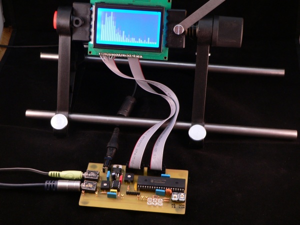
This project introduces a real-time audio spectrum analyzer based on a PIC18F4550 microcontroller. The spectrum frequency analysis is done with a 16-bit Fast Fourier Transformation (FFT) routine coded in C. It uses a 128×64 GLCD to display the FFT waveform of a live audio signal.

“In order to perform a FFT calculation on an audio signal it is necessary to prepare the audio so the PIC18F4550 can sample the signal. The PIC18F4550 provides several analogue to digital converters (ADCs) which can be used to measure a voltage from 0V to 5V with 10-bit accuracy (0-1023). A typical audio line-out signal is an analogue wave with a peak-to-peak intensity of 1V centred around 0V (i.e. it is an AC signal) as shown by the following oscilloscope trace (from pin W2 of the demo board):
In order to correctly sample the signal we have to do two things. Firstly we need to amplify the signal to ensure we can use as much of the 0-5V range as possible. Secondly we have to move the signal’s ground (of 0 volts) to a ‘virtual ground’ of 2.5Vs. This will allow the PIC to sample both the positive and the negative sides of the input signal. To do this the demonstration board uses a simple amplifier IC (the LM386-1). Since the IC is powered from a 0V and 5V power supply it has the handy side-effect of also moving the signal into the middle of our required power range. The LM386-1 was used because it is cheap and simple, however you could use a rail-to-rail opamp to achieve the same thing with a few more external components.”
For further details on the project, visit the author’s website. The link is provided below.
| Read More |
|
|