Lab 13: Read and Write to internal EEPROM

|
|
EEPROM (Electrically Erasable Programmable Read-Only Memory) is a type of non-volatile memory which can be programmed, erased, and re-programmed electrically while it is on the circuit board. A majority of PIC microcontrollers come with some built-in EEPROM which is a great place to store data that should not be lost when the system is powered down. A good example is a digital lock system where the access code can be stored in the EEPROM of microcontroller so that the contents remain intact even after the power supply has been removed. In my ‘Beginner’s data logger‘ project, I used the internal EEPROM of PIC12F683 to store the measured temperature values. In today’s experiment, we will learn how to perform the basic Read and Write operations to the internal EEPROM of PIC16F628A.
Theory
PIC16F628A microcontroller has got 128 bytes of data EEPROM with an address range from 00h to 7Fh. There are four Special Function Registers used to read and write this memory, which are EECON1, EECON2, EEDATA, and EEADR. EEADR holds the address in the EEPROM which you wish to read or write to, while EEDATA holds the 8-bit data that you have just read, or which you wish to write to the EEPROM. EECON1 and EECON2 are control registers that are used to enable the EEPROM read/write operations. We will ignore the details of these registers here because we will be using mikroC compiler for programming, where the built-in library routines for EEPROM operations takes care of configuring these registers. However, you can find the details of these registers in the datasheet of PIC16F628A.
Circuit setup
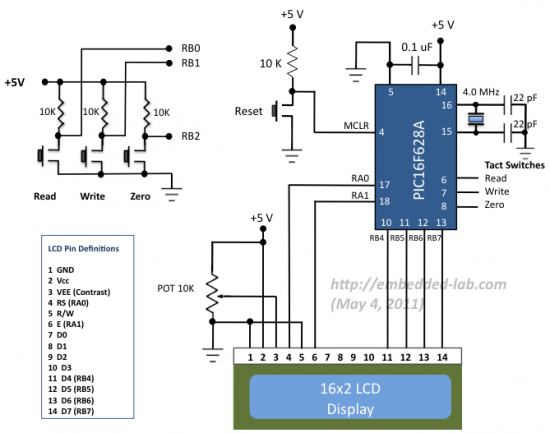
This experiment requires a 16×2 character LCD for display and three tactile switches for user inputs. The circuit diagram below shows the connections of the LCD and the switches with the PIC16F628A microcontroller.
The three tact switches are connected to RB0, RB1, and RB3 pins. The LCD is operating in 4-bit mode and the data pins are driven by RB4 through RB7 pins of PIC16F628A. The LCD RS and E control pins are connected to RA0 and RA1 pins. The functions of the three tact switches are discussed in software section.
Software
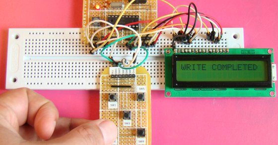
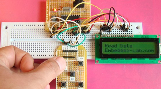
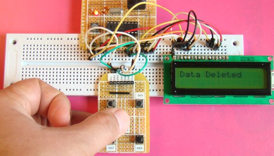
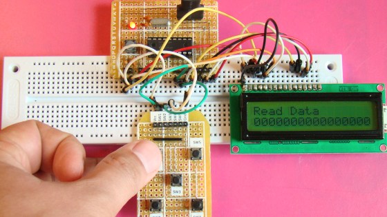
We will write a small application software for PIC16F628A that will do Read, Write and Delete operations to the selected internal EEPROM locations (00h through 0Fh) of PIC16F628A. When the Read button is pressed, the 16 bytes of information stored at 00h-0Fh locations will be read and displayed on the LCD screen. Pressing the Write button will write a character string ‘Embedded-Lab.com’ to these locations, whereas if the Zero button is pressed, the values in these locations will be replaced by all 0s.
The mikroC Pro for PIC compiler provides the following functions for EEPROM read and write operations:
unsigned short EEPROM_Read(unsigned short address) :- returns a byte from the specified address
void EEPROM_Write(unsigned short address, unsigned short data) :- writes the data at the specified address
You can download the complete source code and hex files from the link below.
Output
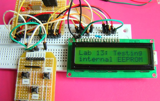
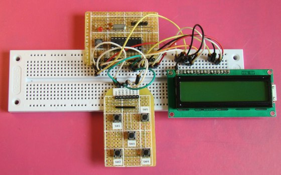
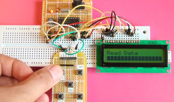
The default values in an erased EEPROM locations are all FFh (255). All 5×10 dots are active on the screen when this value (FFh) is displayed on LCD. So when you first read the EEPROM, which is in an erased state, you will read all FFh (see pictures below). Once the Write operation is completed, turn off the power for a few seconds, then turn it back again, and press the Read button. You will see the character string (Embedded-Lab.com) is still retained inside the EEPROM.
|
|

Dear Sir please guide me with the routine to edit and write a string in eeprom with simple 3 push button. one for changing string character, one for shifting cursor and one for saving data.
Dear R-B,
Hi and thank you so much for your awesome PIC related articles and projects as I greatly learned tons of stuff specially that I am targeting the MikroC IDE/Compiler series as I found it much easier and sensible to learn than the other IDE/Compiler sets. I even think it is way better than the MPLAB by far. HighTech or CCS are lame! 🙂
May I request for an article/project to cover as follows please:
It’d be really useful to have a programmable presets in separate memory banks at run-time where then one could control multiple relays to set multiple devices On or Off, using push buttons which can select the banks in either Up or Down addresses and then another set of push buttons to On or Off any or multiple connected relays to the particular Port(s), where then it can be saved into the selected memory bank as a preset which could be recalled for later use or edit/save again.
I look forward to your approval and article/project post.
Much appreciated in advance.
maselectguitar
@MarcP why don’t you try providing a minimum delay of 30ms between any eeprom_read and or eeprom_write!
Discard first post : here’s the correct code :
HI Raj!
I want to store value into the EEPROM, here’s a part of my code :
char Edata[] = “00?;
unsigned short i, NUM ;
unsigned int ADD; // Start EEPROM Location
void Display_Data(){
Lcd_Out(1,1, hours+48);
Delay_ms(2000);
}
void Write_EEPROM(){
ADD = 0;
for (i=0; i<2; i++) {
temp = EEPROM_Write(ADD+i);
Edata[i] = temp;
}
void Read_EEPROM(){
ADD = 0;
for (i=0; i<2; i++) {
temp = EEPROM_Read(ADD+i);
Edata[i] = temp;
}
Lcd_Out(1,1, EData);
Delay_ms(2000);
}
void main(){
Lcd_Init();
Lcd_Cmd(_LCD_CLEAR); // Clear display
Lcd_Cmd(_LCD_CURSOR_OFF); // Cursor off
Read_EEPROM();
do {
if(!button_set_time){
Delay_ms(300);
hours++;
if (hours == 24) hours = 0;
Write_EEPROM();
Display_Data();
}
while(1);
}
}
the problem is that doesn't seems to work very well, it write unknown character on the lcd screen, can you help me out please?
thank you so much!
It's greatly appreciated!
have a good day!
marC:)
HI Raj!
I want to store value into the EEPROM, here’s a part of my code :
char Edata[] = “00”;
unsigned short i, NUM ;
unsigned int ADD; // Start EEPROM Location
void Display_Data(){
Lcd_Out(1,1, hours+48);
}
void Write_EEPROM(){
ADD = 0;
for (i=0; i<2; i++) {
temp = EEPROM_Read(ADD+i);
Edata[i] = temp;
}
void Read_EEPROM(){
ADD = 0;
for (i=0; i<2; i++) {
temp = EEPROM_Read(ADD+i);
Edata[i] = temp;
}
Lcd_Out(1,1, EData);
Delay_ms(2000);
}
void main(){
Lcd_Init();
Lcd_Cmd(_LCD_CLEAR); // Clear display
Lcd_Cmd(_LCD_CURSOR_OFF); // Cursor off
Read_EEPROM();
do {
if(!button_set_time){
Delay_ms(300);
hours++;
if (hours == 24) hours = 0;
Write_EEPROM();
Display_Data();
}
while(1);
}
}
the problem is that doesn't seems to work very well, it write unknown character on the lcd screen, can you help me out please?
thank you so much!
It's greatly appreciated!
have a good day!
marC:)
Pingback: data storage in EEPROM by PIC microcontrollers.
pls can u send the same program writing with assembly code ?
thanks for you anyway
this line
m = EEPROM_Read(0×00);
is the one which is responsible for reading the memory location, so if it doesn’t get inside the if block what should I do because I’ve enclosed it in curled brackets so eventually it will be inside now the problem remains where is it?
@Matiko,
I would check if the value of sum ever gets more than 2000000000 or not.
Hello R.B can you help me out, I’ve done a project which utilizes most of the tutorial you provide but the problem is that the EEPROm doesn’t store the values. the code is as below, rectify me where am wrong, am using PIC16F887
sbit LCD_RS at RB4_bit;
sbit LCD_EN at RB5_bit;
sbit LCD_D4 at RB0_bit;
sbit LCD_D5 at RB1_bit;
sbit LCD_D6 at RB2_bit;
sbit LCD_D7 at RB3_bit;
sbit LCD_RS_Direction at TRISB4_bit;
sbit LCD_EN_Direction at TRISB5_bit;
sbit LCD_D4_Direction at TRISB0_bit;
sbit LCD_D5_Direction at TRISB1_bit;
sbit LCD_D6_Direction at TRISB2_bit;
sbit LCD_D7_Direction at TRISB3_bit;
unsigned char ch;
unsigned int Voltage_rd, Current_rd;
unsigned long u, i, power, kwh, sum = 0;
unsigned short m, disp = 0;
void Delay2s(){
Delay_ms(2000);
}
void Debounce(){
Delay_ms(100);
}
void main() {
ANSEL = 0b00000100; // RA2/AN2 is analog input
ADCON0 = 0b00001000; // Analog channel select @ AN2
ANSELH = 0;
C1ON_bit = 0; // Disable comparators
C2ON_bit = 0;
TRISA = 0xFF; // PORTA is input
TRISB = 0;
Lcd_Init();
Lcd_Cmd(_LCD_CLEAR);
Lcd_Cmd(_LCD_CURSOR_OFF);
while (1)
{
Current_rd = ADC_READ(2);
i = ((long)Current_rd*40000)/1023;
ch=i/10000; // extract 1.000 I digit
LCD_Chr(1,1,48+ch); // write ASCII digit at 1st row, 10th column
// write ‘.’ at cursor point
ch=(i/1000) %10; // extract 0.100 I digit
LCD_Chr_CP(48+ch); // write ASCII digit at cursor point
LCD_Chr_CP(‘.’);
ch=(i/100) %10; // extract 0.010 I digit
LCD_Chr_CP(48+ch); // write ASCII digit at cursor point
ch=(i /10)%10; // extract 0.001 I digit
LCD_Chr_CP(48+ch);
LCD_Chr_CP(‘A’);
Delay_ms(500);
power = (i*230)/1000;
ch=power/1000;
LCD_Chr(1,10,48+ch);
ch=(power/100) %10; // extract 01.00 P digit
LCD_Chr_CP(48+ch); // write ASCII digit at cursor point
//LCD_Chr_CP(‘.’); // write ‘.’ at cursor point
ch=(power/10) %10; // extract 0.10 P digit
LCD_Chr_CP(48+ch); // write ASCII digit at cursor point
ch=power %10; // extract 0.01 P digit
LCD_Chr_CP(48+ch); // write ASCII digit at cursor point
LCD_Chr_CP(‘W’);
kwh = power * 278;
sum = kwh + sum;
if(sum >= 2000000000)
{
disp++;
EEPROM_Write(0x00,disp);
Debounce();
sum=0;
m = EEPROM_Read(0x00);
Debounce();
if(m < 255)
{
ch=m/1000;
LCD_Chr(2,1,48+ch);
ch=(m/100) %10; // extract 01.00 P digit
LCD_Chr_CP(48+ch); // write ASCII digit at cursor point
//LCD_Chr_CP('.'); // write '.' at cursor point
ch=(m/10) %10; // extract 0.10 P digit
LCD_Chr_CP(48+ch); // write ASCII digit at cursor point
ch=m %10; // extract 0.01 P digit
LCD_Chr_CP(48+ch); // write ASCII digit at cursor point
LCD_Chr_CP('k');
LCD_Chr_CP('w');
LCD_Chr_CP('h');
Delay2s();}
else
{EEPROM_Write(0x00,0);
Debounce();}
}
}
}
Did you read the EEPROM locations after write operation? What does it read? If it reads FF, it means it is never written. May be it never gets inside the if (sum >= 2000000000) block.
mann..i love ur site and all of ur tutorials…i alwayz eagerly wait for ur tutorials as im da beginner in the micrcontroller world….it helped me alot to learn pic….if possible send me ur email id plz…
Pingback: Electronics-Lab.com Blog » Blog Archive » Read and Write to internal EEPROM
hey i love dis site and all of d tutorials….im a great fan of dis site….but i wanna see the tutorials of all the complicated stuffs of microcontroller just like interrupt,capture/compare,i2c…still waiting 4 releasing pic timer and counter part2..
Jacob,
I2C will be the next topic.