A Beginner’s data logger project using PIC12F683 microcontroller
|
|
It is a very simple data logger project based on PIC12F683 microcontroller. The microcontroller reads temperature values from a temperature sensor on a regular interval basis and stores them into its internal EEPROM memory. The recorded temperatures can be later transferred to a PC through serial interface. I originally published this project on electronics-lab.com last summer. I thought this could be a very good learning project for beginners, and so I am posting it here for Embedded Lab’s readers too.
Theory
The sensor used in this project is DS18B20. It is a digital temperature sensor manufactured by Dallas Semiconductor (now MAXIM) that can measure temperature ranging from -55°C to +125°C with an accuracy of ±0.5°C over the range of -10°C to +85°C. The sensor provides the measured temperature (°C) output in user-configurable 9, 10, 11, or 12-bit data corresponding to the desired resolution of 0.5, 0.25, 0.125, and 0.0625 °C. The sensor communicates with a host microcontroller over a 1-wire bus. Readers are suggested to refer the datasheet on Maxim’s website for details on this sensor. Please keep in mind that there are three versions of this sensors, namely DS1820, DS18S20, and DS18B20, and they have some architectural differences. All of them have the same pin configuration and therefore the circuit diagram would be same for all three types. However, some modification in the software may be required while the microcontroller reads the temperature data from them.
PIC12F683 has 256 bytes of internal EEPROM. Each temperature reading is stored as a byte, which means only the eight most significant bits of DS18B20 output is recorded. Therefore, the temperature resolution is decreased down to 1 °C. This temperature logger can store up to 254 temperature values (254 bytes) in its internal EEPROM. The remaining two EEPROM locations are used to store the sampling time and number of samples information. Three tact switches are used to provide user inputs for controlling the operation of the data logger.
Circuit Diagram
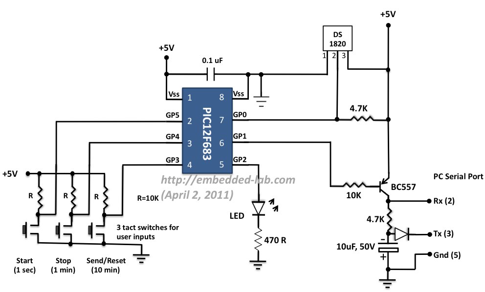
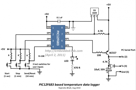
The PIC microcontroller uses its internal clock source operated at 4.0 MHz. The DS18B20 sensor is interfaced to GP0 pin (7) of the microcontroller. An LED connected to the GP2 pin serves as the only display in the circuit to indicate various actions of the data logger. For example, it blinks every time a sample is recorded into EEPROM. The circuit is powered with +5 V derived from a 9V battery using an LM78L05 regulator IC. The LM78L05 circuit is a very common circuit and therefore, it is not shown here.
The three tact switches provide the following functions.
- Start: Starts data logging
- Stop: Stops the logging procedure
- Send/Reset: Transfers data to PC through serial port. However, if it is held pressed for 2 sec or more, the EEPROM locations are cleared and ready for new recordings.
Selection of sampling time
This data logger offers three options for sampling interval: 1 sec, 1min, and 10 min. The selection is made through the same three tact switches. Here is how it works. Suppose if 10 min sampling time is needed, then first turn OFF the power, hold the ‘Send/Reset’ button pressed, turn the power ON, and wait till the LED glows. Once the LED glows, release the button, and the sampling interval is set to 10 min. The new sampling time will be updated to EEPROM location 0 so that in case of power failure, the previous sampling time will be restored. Similarly, the use of ‘Start’ or ‘Stop’ button instead of the Send/Reset one sets the sampling time to 1 sec, or 1 min respectively. With 10 min sampling interval, this data logger can record temperature samples over 42 hours.
Serial Interface to PC
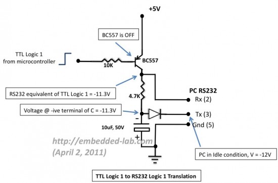
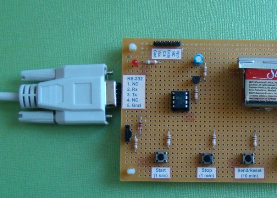
Transferring data to PC through serial port requires a voltage translation circuit to convert the TTL logic levels from PIC12F683 to appropriate RS232 voltage levels. A regular PNP transistor with few other passive components can do this job. The RS232 standard uses a -3 to -12 V for Logic 1 and +3 to +12 V for Logic 0. The required negative voltage is stolen from the TX pin of the RS232 port on PC’s side which is unused as there won’t be any data transfer from the PC to PIC12F683. Under idle condition the TX pin on PC’s side is held high (-12 V). The two figures below describe the operation of converting TTL levels for 1 and 0 to corresponding RS232 levels. The positive terminal of the 10 uF capacitor is grounded because its negative terminal has to deal with a more negative voltage.
Software
The firmware for PIC12F683 is developed in C using mikroC Pro for PIC compiler from mikroElektronika. PIC12F683 doesn’t have built-in hardware UART module for serial communication but the mikroC compiler has built-in library routines to implement software UART through any digital I/O pin of PIC microcontroller. Due to wide use of DS18B20 sensor for temperature measurements, mikroC also provides 1-wire library routines for controlling the operation of this sensor. The built-in functions for communicating with a 1-wire sensor are,
- Ow_Reset is used for reseting sensor;
- Ow_Read is used for receiving data from sensor; and
- Ow_Write is used for sending commands to sensor.
MikroC also provides EEPROM library for read and write operations to internal EEPROM locations. The overall programming is made much easier with the help of these built-in library functions of mikroC. The source code with HEX files can be downloaded from the links below.
Download mikroC project files (for DS18B20 sensor)
Download mikroC project files (for DS1820 sensor)
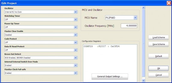
The configuration bits setup for PIC12F683 can be done through Edit Project window in mikroC. The figure below shows the required settings for this project.
Programming sequence
When the circuit is powered on, the LED blinks for 3 times that shows the data logger is turned on and being initiated. The program checks for any key pressed for setting sampling interval. If yes, it identifies the key and store the appropriate sampling interval information to EEPROM location 0. The LED is turned on to indicate that the sampling interval has been set and it’s time to release the pressed key. The program is now inside the main loop. The three switches (Start, Stop and Send/Reset) operate in Interrupt-on-change mode, which means, any time the button is pressed, an interrupt is generated. Pressing the Start button begins data recording. Each time a temperature sample is recorded in to the EEPROM, the LED blinks to indicate that the logging process is going on. Pressing the Stop button will interrupt this process, while Send will initiate the serial transfer of recorded samples through GP1 pin (6). If the Send button is pressed for more than 2 sec, the entire EEPROM locations will be cleared.
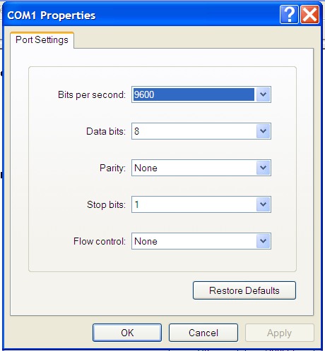
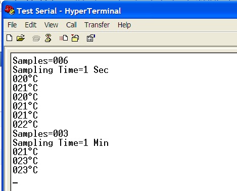
On PC’s side, the hyperterminal program is used to receive logged temperature data from PIC12F683. The rate of data transfer is set to 9600 baud on both end. The figure below shows the hyperterminal settings for this project.
Conclusion and future work
A simple data logger project was demonstrated using a PIC12F683 micrcontroller and DS18B20 temperature sensor. A number of improvements can be done with this project, such as adding an external EEPROM for expanding its recording capacity. A separate application program can be developed on PC’s side to receive the serial data from the logger and generate temperature vs time plots. A real time clock chip can also be added in the project to keep record of the actual time stamp. A bigger PIC with more I/O pins would be more appropriate for implementing these additional features.
Update (Dec 28, 2012)
Peter Albeda from The Netherlands has made some improvements in the firmware provided here. His version of software has the following improved features:
1) Support for negative temperatures
2) When you delete the data, it now no longer resets the sample time
3) Deletes the leading zero’s while sending data to PC over a serial link
Download Peter’s version of source code and HEX files
Update (Nov 29, 2014)
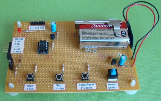
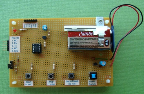
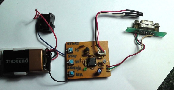
Fabian (from Argentina) has successfully built this project and has shared a picture of his final working prototype.
|
|


sir
i have a temperature data logger with rs 232 communication , when i connect to my laptop with hyperterminal
software i can view the data comming to my laptop
now i need to store it in my pen drive directly from rs 232 port in the instrument is there any hard ware please help me
regards
prasad
Pingback: World's Top 20 PIC microcontroller projects ideas for enthusiasts
sir
this is my mini project. i want to all component related to this project please…………
thanks sir
What will be the frequency of such a type of logger ckt..?????,?
thank you very much for this project.i wanted to ask if we can use any other pic instead of PIC12F683
?thnx u in advance
Hi peggy,
you can do this using PIC18f4520 microcontroller as well. Even arduino boards will work for this.
thank you very much for this project.i wanted to ask if we can use any otheer pic instead of PIC12F683
?
I did it with Peter’s code, it work really well, thanks for the post. I was thinking change the way it send numbers, I like to take off the carry feed line but I not know how to compile with microc so it will take a time.
Thanks again
Good job, take a look at my version: https://www.youtube.com/watch?v=-JlZPPUafio
Sir,I am doing this as my mini project. May i know the design calculations? I mean how you decided the values of resistors capacitors?
Your job is excellent , learning a lot from your site. – See more at: http://embedded-lab.com/blog/?p=2236#sthash.J10L5yX4.dpuf
Thanks for this great product.I use DS18B20 and the temperature I logged
is 4°C smaller what is the real.
Another : can I 10 min intervall change 6 min?
Once again, thanks Berez
Sorry for poor english I am from Hungary…
is there any pic including rtc and bigger eeprom? thanx for the example, i’m looking for such a datalogger which stores little more samples (hourly sample for 1-2 month).
Many, many thanks for posting it. As the source code is included, it is an excellent chance to try out some improvements. I implemented the following improvements very easily, as the code is written clearly:
1) I added support for negative temperatures
2) When you delete the data, it now no longer resets the sample time
3) I deleted the leading zero’s
I also very much liked the easy rs232 converter you added!
Once again, thanks
Peter
Hi Peter,
That’s a great improvement. Would you like to share your code with other readers? If yes, you can email me a zipped folder with source and HEX files at admin (at) embedded-lab.com.
Can you tell me from where I can download free micr-c for AVR and PIC.
please reply,
Your job is excellent , learning a lot from your site.
regards,
Uttam
From here: http://www.mikroe.com/eng/products/view/7/mikroc-pro-for-pic/
sir , which value diode u r using in driving circuit at Tx pin(2).plz rpl..
1N4004 or any other normal diode will work.
I was made this project for my mini pro. seminar. I have some problem in stop button, when i press start led blinks for 3 times it starts logging but when i press stop led cant blink and when send press it cant send any data to hyperterminal as i set reqr. configuration of hyper… sir please tell me soln.
sir, i want to info about project hex code that u r given from link on this page of sensor DS18B20 bcoz pic has internal program memory 2K and HEX code file is about 12K then how can i burn it in pic. may i know which kit/software did u use to transfer the data to the pic. plz reply…
sujit,
The size of an ASCII file is different than the size of the HEX content inside it. Use PICkit2 to transfer the HEX file into MCU.
hye sir ,can explain where can get the hyper terminal software and actual use of it ?? plz reply sir
hi sir… i need a good n simple circuit n code for my miniproject… any suggestions… reply asap…thank you
hey,i just wanna ask, is there a temperature sensor build in in this circuit and can i use this data logger and merge it with digital tachometer circuit…so that i can store my rpm data?????please reply asap. thank you
The temperature sensor used in this project is DS1820.
hi sir
i am santhosh
thanks for your reply
may i know which kit did u use to transfer the data to the ic
I have a couple of USB programmers that I use to program the PIC. You can find them here:
http://www.piccircuit.com/26-ica01-usb-pic-programmer-set.html
http://www.mcumall.com/comersus/store/comersus_viewItem.asp?idProduct=3141
http://www.mikroe.com/eng/products/view/18/picflash-with-mikroicd-support/
hi sir,
i am santhosh doing a final year project in temperature data logger
i want to know how to add a external memory to increase the memory capacity
Santosh,
An external EEPROM can be added through I2C interface. Check out my tutorial:
http://embedded-lab.com/blog/?p=2583
Pingback: A Beginner's data logger project using PIC12F683 microcontroller … | Data loggers details
Pingback: PIC-based temperature logger with onboard storage | House of Mods
Pingback: PIC-based temperature logger with onboard storage - machine quotidienne
Pingback: PIC-based temperature logger with onboard storage « Black Hat Security
Pingback: PIC-based temperature logger with onboard storage - Hack a Day
Pingback: Electronics-Lab.com Blog » Blog Archive » A Beginner’s data logger project using PIC12F683 microcontroller