chipKIT Tutorial 4: Interfacing a character LCD

|
|
Liquid Crystal Displays(LCDs ) are a very popular output device for displaying graphical and alphanumeric data in microcontroller based systems. They can also provide an interactive input interface to the users. The most common type of LCD controller used by hobbyists is the Hitachi 44780, which provides a relatively simple interface between a processor and an LCD. The purpose of this tutorial is to describe how to interface Hitachi 44780–based LCDs with the chipKIT Uno32 board to display alphanumeric information.
Theory
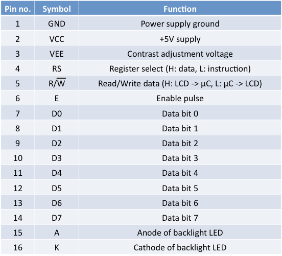
Hitachi 44780 based LCDs come in different connector shapes. The most common one uses 16 pins in a row, with pin centers 0.1″ apart. The pinout is listed in the table shown below.
The interface is a parallel bus that allows simple and fast reading/writing of data to and from the LCD. The ASCII code to be displayed is 8 bits long and is sent to the LCD either 4 or 8 bits at a time. Eight-bit mode is best used when speed is required in an application and at least 10 I/O pins are available. Four-bit mode requires a minimum of 6 bits. To wire a microcontroller to an LCD in 4-bit mode, just the top 4 bits (DB4–7) are written to, with first the high nibble followed by the low nibble of the byte. Besides the data bus, there are three control lines:
- Register Select (RS), which is used to select whether data or an instruction is being transferred between the microcontroller and the LCD. It is 0 for a command and 1 for data.
- Read/Write (R/W), which determines data direction. If the bit is set, then the byte at the current LCD cursor position can be read or written. For most applications, there really is no reason to read from the LCD, and therefore the R/W pin can be tied to ground.
- Enable (E), which provides a clock function to synchronize data transfer. The data appeared at the data pins is latched into the LCD by pulsing the E (Enable) input.
The Hitachi HD44780 controller inside the LCD must be initialized according to the data and display options required. In this tutorial, the data is being sent in 4-bit mode and thus it will require 6 I/O pins of chipKIT Uno32.
Circuit setup
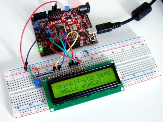
Shown below are the Uno32 pins that are used to drive the 4 data bits and two control lines of the LCD. The R/W control pin of the LCD is permanently tied to ground. A 5K potentiometer is used to set the contrast of the LCD display. The RS and E control lines go to I/O pins 9 and 8, respectively, whereas the data bits are driven through pins 4 through 7. Note that the Hitachi 44870 based LCDs are mostly a +5V device, so it must be powered with the +5V supply from Uno32. The chipKIT Uno32 provides 3.3V at its output pins for logic HIGH. The question is whether this output voltage is high enough to be recognized as a logic high input by a +5V device? Some +5V devices do and some don’t. I have tested with many Hitachi 44870 based LCDs, and they did recognize the 3.3V input as logic high. The 56? series resistor in the circuit is to limit the current through the LCD backlight LED.
Writing sketch
The chipKIT MPIDE comes with a library called LiquidCrystal.h that allows the Uno32 board to control LCDs based on the Hitachi HD44780 (or a compatible) chipset, which is found on most text-based LCDs. The library works in either 4- or 8-bit mode. You can find details of this library and supported functions in the original Arduino reference page. Given below is the complete chipKIT sketch for demonstrating LCD interface.
/* Tutorial 5: Interfacing an HD44780 based character LCD Description: Explore the various LCD display commands available through the built-in LiquidCrystal library. Board: chipKIT UNO32 */ // Include the LiquidCrystal library #include <LiquidCrystal.h> // Initialize the LCD interface pins in the following sequence // RS, E, D4, D5, D6, D7 LiquidCrystal lcd(9, 8, 7, 6, 5, 4); void setup() { // Define the number of columns and rows of the LCD lcd.begin(16, 2); } void loop() { // lcd.print() demo lcd.print("chipKIT-LCD DEMO"); lcd.setCursor(0, 1); // Set cursor to col 0 row 1 lcd.print(" HELLO WORLD!"); delay(2000); lcd.clear(); // Clear the display // Scrolling text LEFT lcd.setCursor(5, 0); lcd.print("SCROLL LEFT"); delay(500); for(int i=0; i<16; i++) { lcd.scrollDisplayLeft(); delay(500); } lcd.clear(); // Clear the display // Scrolling text RIGHT lcd.setCursor(0, 0); lcd.print("SCROLL RIGHT"); delay(500); for(int i=0; i<16; i++) { lcd.scrollDisplayRight(); delay(500); } lcd.clear(); } |
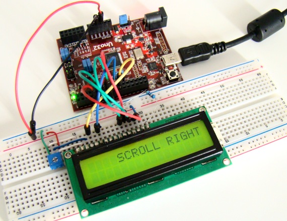
At first you need to create an LiquidCrystal object and define its pin numbers. For example, in the above code LiquidCrystal lcd(9, 8, 7, 6, 5, 4) defines lcd as an LiquidCrystal object with its RS, E, D4-D7 pins connected to the I/O pins 9, 8, 7, 6, 5, and 4, respectively, of Uno32. Inside the setup function, the LCD is initialized using lcd.begin(). The two parameters inside the parenthesis defines the number of columns and rows of the display. The LCD used in this example has 16 columns and 2 rows. The lcd.print() command prints text to the LCD at a current cursor position. In order to mover the cursor on the LCD, use lcd.setCursor() command. The LiquidCrystal library also features text scrolling on the LCD. The above demo sketch displays some text and scroll it left and right. For a complete description of the LiquidCrystal library, visit Arduino reference page.
Output
|
|


