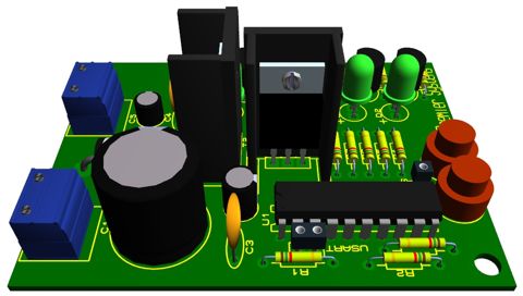
A simple idea of making a digitally controlled variable power supply.

|
|
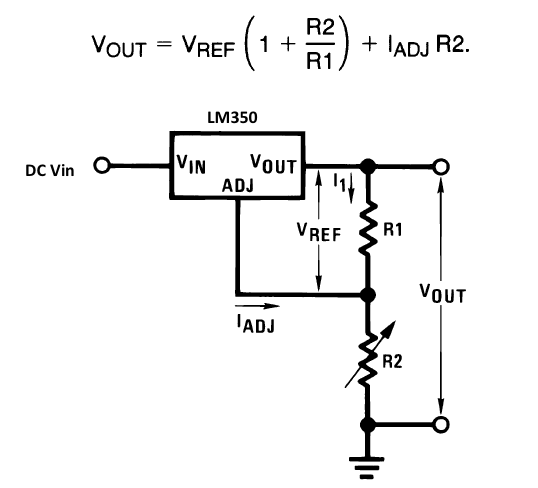
A variable power supply is a very useful tool for designing and testing electronics circuit. There are varieties of adjustable regulator IC’s available to generate a variable DC power supply. They normally use a two-resistor feedback network at the output to control the output voltage. If one of the resistor is replaced by a potentiometer, the output voltage can be easily adjusted as required. LM350 is one of such adjustable regulators that is capable of supplying in excess of 3A over a 1.2V to 33V output range, and is very easy to use. It requires only 2 external resistors to set the output voltage (shown below). Read the datasheet for more details on LM350. This project also uses an LM350 regulator with a microcontroller to control the output voltage.
The role of the microcontroller in this project is to select an appropriate resistor for R2 from a resistor bank to control the output voltage. There are 5 resistors in the bank each of which is controlled by a seperate I/O pin from a microcontroller. The microcontroller turns a bipolar junction transistor ON and OFF to connect and disconnect a resistor across the R2 terminal points. The 5 individual resistors, seperately controlled by the microcontroller, can give rise to 32 different equivalent resistance values for R2, which means 32 different output voltages.
| Read More |
|
|

