Author Archives: R-B

Lab 20: Interfacing a KS0108 based Graphics LCD (Part 2)

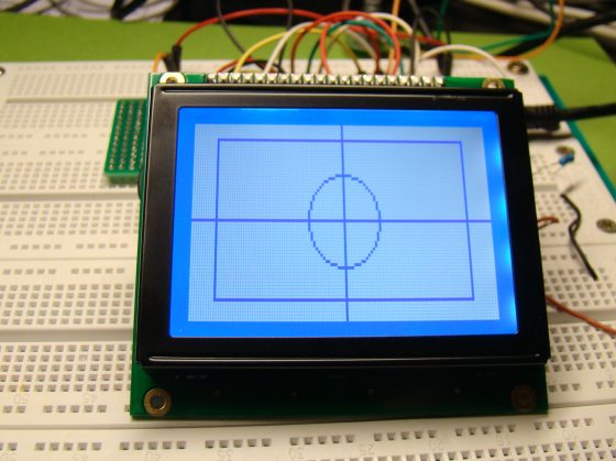
In the first part of this tutorial, we discussed about Winstar’s WDG0151-TMI GLCD module, which is a 128×64 pixel monochromatic display built with KS0108B and KS0107B compatible display controllers. The module was interfaced to a PIC16F887 microcontroller and a test program was written in C to demonstrate how to implement the KS0108 instruction set in the firmware of PIC to activate display pixels on the screen. We wrote our subroutine programs that would turn the GLCD on, move the display location to a specified row and column, and draw a pixel at a given coordinates. You might have realized it by now that how much of effort is required to write the firmware for just plotting a point on a GLCD screen. Today’s discussion will focus more on using the built-in GLCD library routines of mikroC Pro for PIC compiler, which will make your life a lot easier if you are using a graphical LCD in your project.

Using MikroC Pro for PIC GLCD library

Read more

Breadboard module for 18-pin PIC16F microcontrollers (PCB version)

Because of their compact size, ease of use and many built-in peripherals, the 18-pin PIC16F series processors (PIC16F628A, PIC16F88, and now PIC16F1827/47) have always been my favorite microcontrollers. Many of my projects and tutorials written in this blog also use PIC16F628A and PIC16F1827 microcontrollers. As I will be using them more in the future too, I thought of making some PCB versions of my breadboard module for PIC16F628A with some modifications. I used Iteadstudio’s PCB prototyping service for this, and I would say the PCBs turned out really well for the price I paid. I used their 2 layer 5cm x 5cm service and got 10 PCBs for less than $15, including shipping to the United States.

Mini breadboard module for 18-pin PIC microcontrollers

Read more

Lab 20: Interfacing a KS0108 based Graphics LCD (Part 1)

The use of a graphical LCD (GLCD) drastically changes the look of your project. It provides more freedom for presenting data than the HD44870 based character LCDs. Today we will see how to interface a KS0108 (name of the display controller chip) based GLCD to a PIC microcontroller. This experimental tutorial is divided into two parts. In the first part, we will see how to write a firmware for the PIC microcontroller to initialize the GLCD and send data to plot points and lines on the screen. The second part will focus more on exploring the built-in GLCD Library of mikroC Pro for PIC compiler to display more complex texts and objects. Since GLCDs are real resource hungry devices (in terms of required I/O pins and memory), a bigger size PIC microcontroller (PIC16F887, which has 36 I/O pins and 14KB flash memory) is selected for this experiment. I am using MikroElektronika’s UNI-DS6 development board to demonstrate this project, but the circuit setup can also be made on a breadboard.

Interfacing a 128x64 pixels GLCD

Read more

Setting up the CCS v4 build and debug environment for TI MSP430 Launchpad

Last year, Texas Instruments (TI) released industry’s lowest cost (only $4.30) microcontroller development kit named Launchpad. It is a complete development tool for rapid prototyping with TI’s ultra-low power MSP430 Value Line MCUs. I also bought a Launchpad kit several months ago but haven’t really looked into it. Last weekend, I spent a couple of hours reading about the MSP-EXP430G2 experimenter board (that comes with the Launchpad kit) and the Code Composer Studio (CCS) software tool. CCS is an integrated development environment (IDE) to develop and debug applications for TI’s embedded processor families. As always, a “Hello World” program is the best thing to start with any new development platform. If you ran it successfully, it means you have setup the compiler and the programmer/debugger correctly and you are all set to go. Here’s a step-by-step guide to set up the CCS v4 build and debug environment for the MSP-EXP430G2 experimenter board.

TI's MSP430 Launchpad board

Read more

Build a digital spirit level using a SCA610 accelerometer

A bubble or spirit level meter is a handy tool to find whether a surface is horizontal or vertical. It is often carried by civil engineers, mechanical engineers, surveyors, carpenters, and many other professionals whose work involve precise alignments of horizontal and vertical planes. Original spirit levels had two banana-shaped curved glass vials at each viewing point and were much more complicated to use. Mechanical spirit level meters are still available both in 1D and 2D formats. However at present time their electronic counterparts have also emerged and are even available in modern Android equipped cell phones. It’s from there I got my inspiration to make a very simple digital spirit level. Here’s a demo of such an electronic spirit level made by using a Microchip PIC16F684 micro, a SCA610 accelerometer and a handful of other discrete components.

Digital spirit level meter

Read more

« Older Entries Recent Entries »