Another RPi-based solar powered weather station
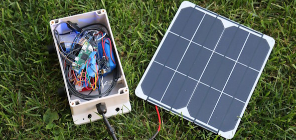
Brian Masney from Morgantown, WV has designed a full-featured solar powered weather station that includes sensors for measuring rain, wind, temperature, humidity, and pressure. It runs on a Raspberry Pi Zero running the latest Raspbian Testing Lite and is powered by a 6600mAH 3.7V lithium ion battery that is charged using a 6V 9W solar panel.
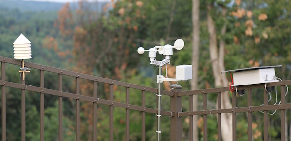
Solar powered weather station
The solar panel is attached to the top of the project box using several large pieces of Velcro. More information about the solar setup can be found on Adafruit’s Website. Be sure to connect the PowerBoost 1000 to the battery charge output pins; not to the load terminal. This is because the solar panel can put out 6V however the PowerBoost can only accept a maximum input voltage of 5.5V. See this post on the Adafruit forums for more details. There should not be anything hooked up to the load terminal on the charger. I fried a Pi Zero and a PowerBoost 1000 on a bright, sunny afternoon with the PowerBoost hooked up to the load terminal.
To reduce the power usage of the Raspberry Pi, the LED and display on the Pi was disabled.
powertop --auto-tunewas used to enable other power saving features. See the files systemd/power-savings.service and bin/power-savings for details. The power requirements could be reduced even further by desoldering the various LEDs on the solar charger and PowerBoost 1000.