Making a simple ESP8266-based clock synchronized to NIST server
|
|
Internet has made it quite easy for computers to synchronize their clocks to an accurate clock value generated by a remote server. In the United States, the National Institute of Standards and Technology (NIST) provides official time. NIST disseminates the time using several methods, which include broadcasting over short-wave and long-wave radio, telephone dial-in services (ACTS), and Network Time Service (NTS) over the internet. This article describes a ESP8266-based clock project that utilizes NIST’s NTS service to retrieve accurate time information and display it on a 4-digit seven segment LED display. The time is synchronized to the NIST server after every 2-minute interval. The display also contains a colon that blinks every second.
ESP8266 seven segment LED clock
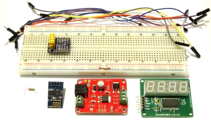
Things you will need
This project uses ESP-01 module to connect to the NIST time server through your local home/office WiFi and display time on a serially-driven seven segment LED display. The WiFi network name (SSID) and password are hard-coded into the firmware that is loaded into the ESP-01 module. The firmware for this program is developed using the Arduino IDE. The following hardware items are required to build this ESP8266-driven internet-connected seven segment LED clock.
1. ESP-01 module
3. Serial 7-segment LED display
4. 5V/3.3V regulated power supply board
5. USB-UART module to program ESP-01
6. 1K resistor, breadboard and wires
Things you will need
ESP-01 module is not breadboard friendly, so you will need an external adapter to use it on a breadboard circuit. You can either make one by yourself or buy a ready-made from our Tindie store.
The seven segment display used in this project is MAX7219-powered and can be bought from our Tindie store. It has a high-quality 4-digit display (Yellow) with a colon and decimal digits. Check out the documentation page for more details on the connections and wiring details of this product.
The ESP-01 module draws ~300 mA of current during WiFi operation. Therefore, you will need a regulated 3.3V (rated 500mA or higher) power supply to power the ESP-01 module. Also, the seven segment display module will require a regulated 5V power supply. I am using our Dual (5V/3.3V) Regulated Power Supply board for this project. This power supply provides 5V and 3.3V outputs with 500mA capacity for each.
The connections between the ESP-01 module and the LED display are shown below. The MAX7219-based seven segment LED display requires 3 I/O pins to drive all the segments. The GPIO2 and GPIO0 I/O pins of ESP-01 are used to drive Data (DIN) and Clock (CLK) pins of MAX7219. The LOAD pin of MAX7219 is driven by the TX pin of ESP-01. The TX pin is actually GPIO1 and can also be used as I/O pin. Note that you cannot use Serial print statements while writing the firmware for this project after using the Tx pin as a I/O pin. You can also consider using a 3.3V-to-5V level shifter in between the MAX7219 and ESP-01 modules, but it has worked perfectly fine without it, as long as you power the MAX7219 with 5V.
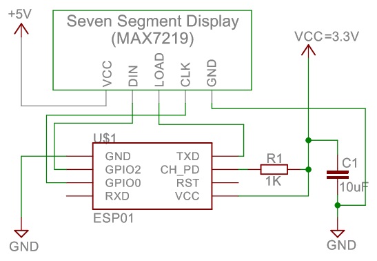
Circuit diagram for ESP8266-based clock
The above circuit diagram does not show connections between the ESP-01 and USB-UART modules for programming the ESP-01. You can google “how to program esp-01” to find information on programming a ESP-01 module using an USB-UART module. Few articles that describe this process are listed below:
http://www.esp8266.com/wiki/doku.php?id=getting-started-with-the-esp8266
https://www.hackster.io/glowascii/esp8266-programming-jig-5afd03
Note that you need to disconnect the ESP-01 module from the above circuit to upload the clock firmware (provided later in this article) as the TX and GPIO0 pins will be required during programming.
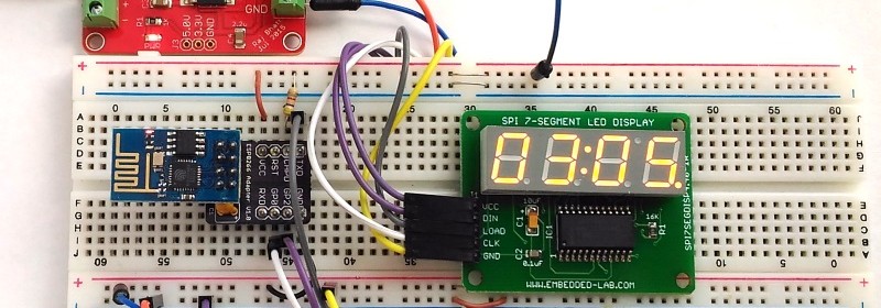
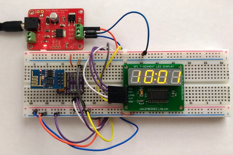
The following figure shows the actual setup of the clock circuit on a breadboard after the firmware has been uploaded to the ESP-01 module.
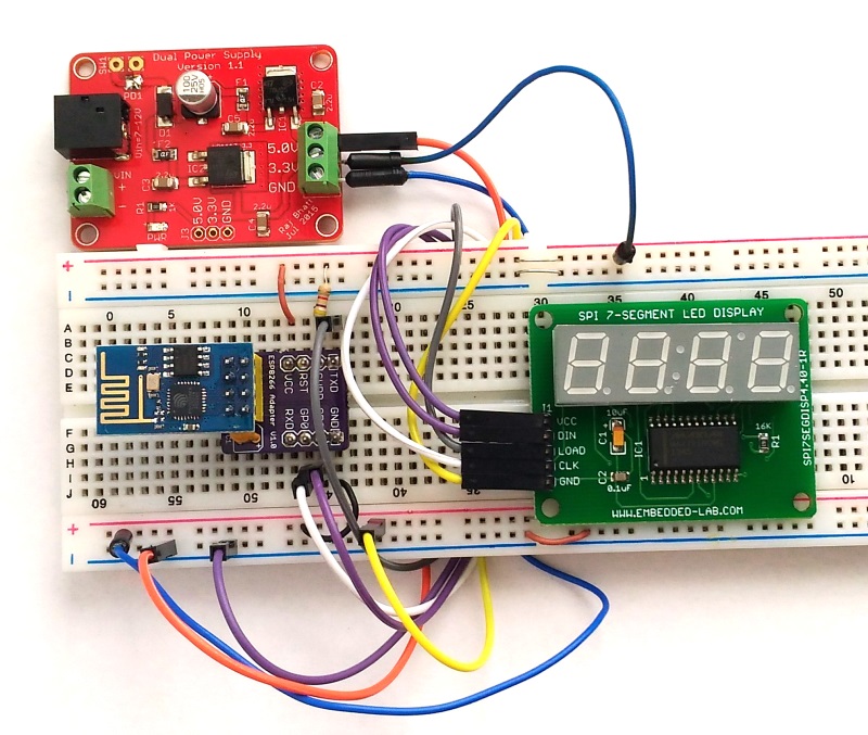
ESP8266-based clock circuit setup on breadboard
Firmware
With the availability of Arduino core for ESP8266, it’s been possible to develop programs for ESP8266 using the popular Arduino IDE. It allows us to use most of the familiar Arduino functions and libraries, and run them directly on ESP8266. If you haven’t setup your Arduino IDE to support ESP8266, you can find the information to do that here.
You can find several examples online on the implementation of Network Time Protocol (NTP) in Arduino to fetch time from NIST server. NIST operates several time servers for its Internet Time Service (ITS). The list of these time servers and their IP addresses can be found here. Note that NIST does not allow queries to any of their servers more frequently than once every 4 seconds. In this project, the queries are made once every two minutes. In between the queries, which is a 2-minute interval, the time is kept running locally using the delay() routine. You can download the ESP-01 Firmware for this project from the following link.
Download Code for ESP8266 InternetClock_ESP01
Important notes:
- The time-fetching code was derived from Kev_MacD‘s instructables on Steampunk ESP8266 Internet connected Clock.
- In the code, you need to change the network SSID and password to match to your network.
- In addition, you also need to adjust the GMT offset for your location to get the correct local time. For example, the GMT offset for EST is -4 (int hours_Offset_From_GMT = -4;).
- The display part of the code uses the LedControl library. You can read my previous article on how to use MAX7219-based seven segment displays with ESP8266.
- The time is displayed in 12 hour format. The decimal digit of the first digit from right is a PM indicator, which means it will turn on for PM hours.
- The colon segments will blink at 1 Hz.
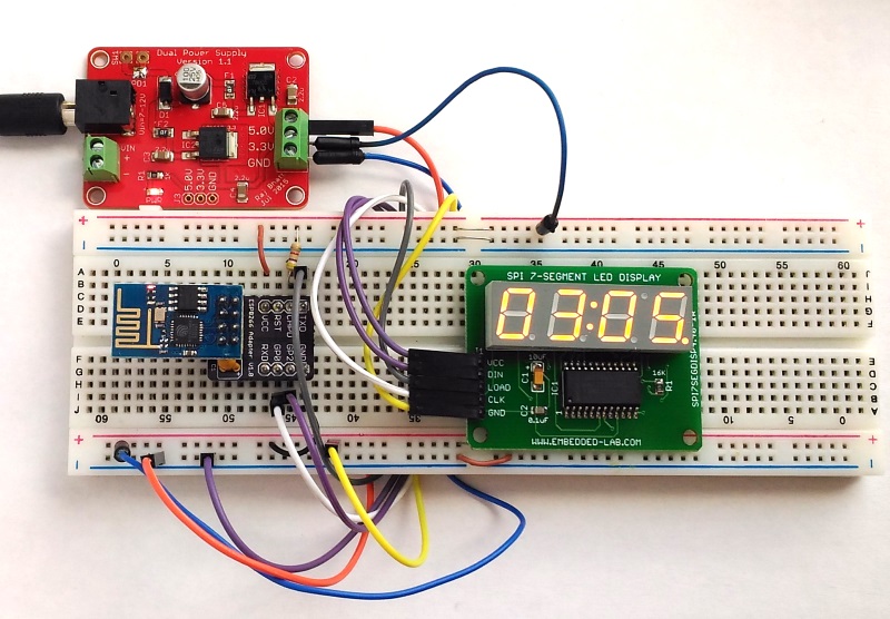
ESP8266 WiFi clock showing time 3:05 PM
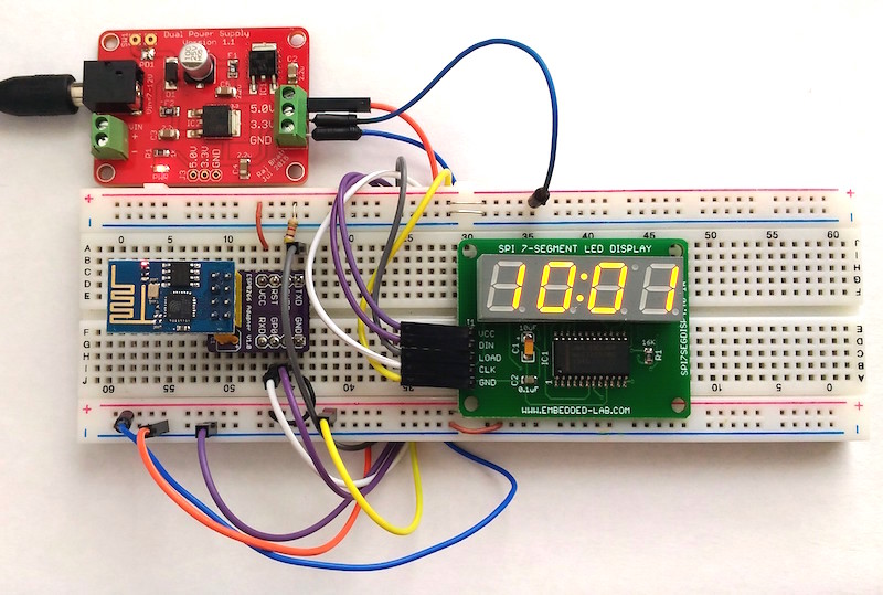
Time shown is 10:01 AM
Buy MAX7219 serial LED display
Buy dual (3.3V/5.0V) regulated power supply
|
|
Pingback: ESP8266-based Clock Synchronized With Network Time Service - Electronics-Lab