Author Archives: R-B

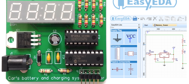
EasyEDA: A free cloud-based tool for schematic capture, PCB layout, and circuit simulation

I have been using Eagle CAD for many years now and it’s still my favorite tool for circuit layout and PCB designing. Eagle has been around for more than two-and-a-half decade, and during this time it has built an impressive set of component library, which is a huge time saver for PCB designers. Today, we live in a golden age of cloud-computing and the tools available to us now are more versatile than ever. A few weeks ago, I had an opportunity to try a new electronics design automation (EDA) tool called EasyEDA. It is a free web-based tool for schematic capture, PCB layout, and circuit simulation. The best part of any cloud- or web-based development tool is that it runs on a remote server (no worries to install on local machines), always up to date, and is accessible from anywhere through internet. EasyEDA is a zero-install cloud-based EDA application; all you need is a web-browser and internet connection and you are ready to draw circuits, run SPICE simulation, design PCBs, and even place an order for fabricating PCBs. I have a very pleasant learning experience playing with it for a couple weeks and I found the learning curve wasn’t too steep.

sdsad

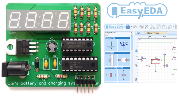
EasyEDA offers free schematic capture, SPICE Simulation, and PCB design

Read more

Development board for PIC16F1938

The PIC16F1938 is a versatile 28-pin MCU belonging to Microchip’s extreme low power microcontroller family featuring nanoWatt XLP technology, 28KB of programming memory, 1KB of RAM, 11 ADC channels, and tons of other peripherals. A while ago, I designed a development board for this MCU and I thought it would be worth sharing this design here. The development board features an onboard USB-UART bridge to support the ds30 Loader for easy programming of the PIC MCU. All I/O pins are accessible through 2×5 headers.

PIC16F1938_1

PIC16F1938 development board

Summary of Features:

  • On-board 5V and 3.3V regulators
  • Support both 5V and 3.3V MCUs. The power supply option is selected through a slide switch (SW1).
  • FT232RL USB-UART bridge
  • PIC16F1938 runs at 16 MHz external resonator
  • PIC is preloaded with the ds30 Loader (bootloader)
  • All I/O pins are accessible through 2×5 male headers. Each header connector has VCC and GND pins.
  • ICSP connector for PICKit2 or 3
  • On-board LED connected to RA0 pin.
PCB

Top layer of PCB

PIC16F1938_2

Assembled PIC16F1938 development board

Download EagleCAD Files

Download ds30Loader Bootloader for PIC16F1938

The pre-compiled HEX file for bootloader can be found inside the dist folder.

Following is the list of components used in this development board.

BOM

BOM

Hookup guide for 16×32 RGB LED panel – Part 3

In this third part of the 16×32 RGB LED panel hookup guide, we will run some demo sketches with Arduino Uno to display basic text and animation on the 16×32 RGB LED matrix. These demo programs use Adafruit’s RGBMatrixPanel Library are found inside its Example folder. The wiring between the RGB panel and Arduino Uno is discussed in detail in the previous parts of this 3-part tutorial.

Click here to read Part 1 of this tutorial
Click here to read Part 2 of this tutorial
Click here to buy this kit from our US Tindie store

Get this RGB panel kit from our Elecrow store in China!

After wiring up the RGB panel to Arduino Uno through the connector shield, it’s time now to run some text and animation graphics on the RGB matrix panel. This would first require the following two libraries to be downloaded and installed.

Adafruit GFX Library

Adafruit RGB Matrix Panel library

There are multiple ways of installing these libraries to your computer’s Arduino IDE tool. Please read this installation guide from Arduino website if you haven’t experienced it before. The RGB Matrix Panel library has built-in routines to illuminate selected pixels, construct line, rectangle, and circle, and print alphanumeric characters in two different font sizes.

After the succesfull installation of the above libraries, we can now try out some of the examples included in the library package. On Arduino IDE, load the testshapes_16x32 example from File→Examples→RGBmatrixPanel→testshapes_16x32 and upload to the Arduino Uno board. This example illustrates how to draw pixels, rectangles, and circles with chosen pixel color at specific locations. The program ends with printing some 5×7 pixel size text characters along two rows of the RGB panel. Power up the RGB panel and Arduino Uno and observe the program out in action.

out

testshapes_16x32 demo output

There are three more 16×32 RGB examples included in the library package: testcolors_16x32, plasma_16x32, and scrolltext_16x32. Because the Arduino pin assignments implemented in our RGB connector shield to connect the RGB LED panel match with the default setting of these examples, they can be just run by simply uploading to the Arduino Uno board.

16x32 plasma demo

16×32 plasma demo

These RGB panels have unlimited applications. In my next article, I will write about constructing a colorful real-time clock display plus thermometer and hygrometer. Stay tuned!

Real time clock and thermometer demo

Real time clock and thermometer demo

Hookup guide for 16×32 RGB LED panel – Part 2

This is the second part of the 3-part article on how to hookup our 16×32 RGB LED panel kit to Arduino Uno.

Click here to read the first part

Step 3: Connecting the LED panel to the RGB connector shield

The pin arrangement of the 2×8 IDC port (IN) on the back side of the RGB panel are shown below (image taken from Adafruit’s tutorial page).

Pin arrangement of 16x32 RGB input IDC port (from Adafruit)

Pin arrangement of 16×32 RGB input IDC port (from Adafruit)

The 12 I/O pins of Arduino that are used to drive these signal lines are listed in the following table.

RGB panel and Arduino Uno pin mapping

RGB panel and Arduino Uno pin mapping

Read more

Hookup guide for 16×32 RGB LED panel – Part 1

RGB LED panels are a great way of displaying colorful texts, images, and animation. In this 3-part tutorial, I am going to demonstrate how to hookup our 16×32 RGB LED panel kit to an Arduino Uno board and run some demo sketches. Our 16×32 RGB LED matrix panel kit includes everything you need to connect it to an Arduino Uno board. The kit includes:

  • One 16×32 RGB LED matrix panel
  • One RGB connector shield for Arduino Uno
  • One IDC cable to connect the RGB matrix panel to the RGB shield
  • One power supply connector for the RGB matrix

Note that the power supply required to power the LED panel is not included in the kit. You will need a regulated 5V DC power supply with enough current sourcing capability (~2A) to power the RGB panel. If you could get the power supply with a 2.1mm x 5.5mm DC barrel output, that would be a plus. In case you don’t have such a power supply, we will show you later how to use a standard cellphone/tablet wall charger with an USB port for powering the LED panel.

Get this RGB panel kit from our Tindie store in USA!

Get this RGB panel kit from our Elecrow store in China!

16x32 RGB LED panel kit

16×32 RGB LED panel kit

Read more

« Older Entries Recent Entries »