Hookup guide for 16×32 RGB LED panel – Part 2
|
|
This is the second part of the 3-part article on how to hookup our 16×32 RGB LED panel kit to Arduino Uno.
Click here to read the first part
Step 3: Connecting the LED panel to the RGB connector shield
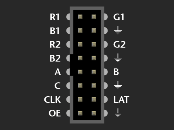
The pin arrangement of the 2×8 IDC port (IN) on the back side of the RGB panel are shown below (image taken from Adafruit’s tutorial page).
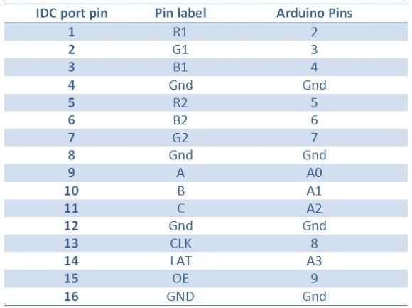
The 12 I/O pins of Arduino that are used to drive these signal lines are listed in the following table.
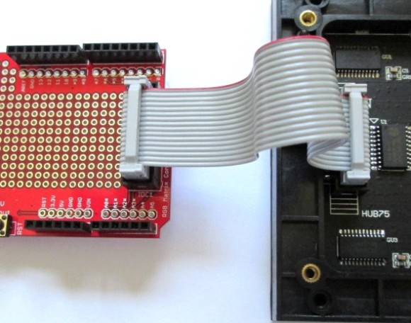
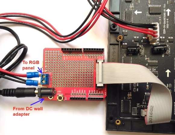
Use the 2×8 IDC cable provided in the kit to connect the 12 I/O pins of Arduino Uno to the LED panel IN port. The IDC connector is polarized, so you don’t need to worry about plugging it in a wrong way.
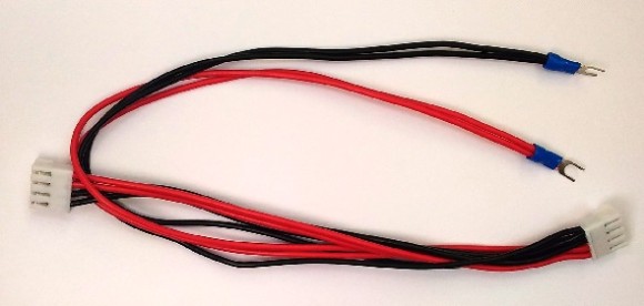
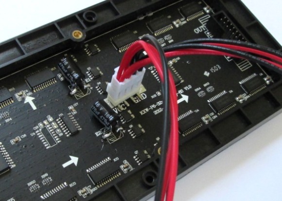
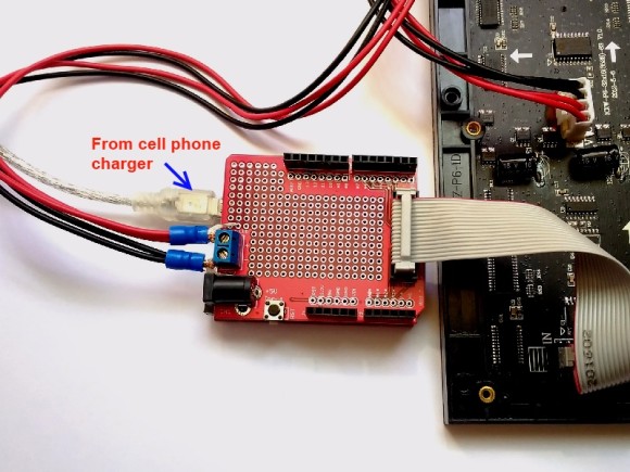
The power supply cable included in the kit has a polarized Molex-type connector (that matches with the power supply connector on the RGB panel) on one end and a pair of spade terminals on the another end. It is used to connect the +5V and GND pins on the back of the RGB panel to the 2-pin screw terminal block on the Arduino shield.
The Molex-type connector is polarized so that Red wires go to the VCC pins and Black ones go to the GND pins as shown below.
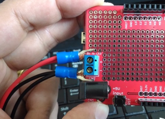
The spade terminals on the other end of the power supply cable are tied to the 2-pin terminal block on the shield as shown below.
Note: Red goes to “+” and Black goes to “–“.
Step 4: Power supply
The 16×32 RGB panel, when all LEDs (16x32x3=1536) are turned on (which means all LEDs are bright white), consumes little over 3A of current. But in practice, that does not happen (unless it is done intentionally), and one 16×32 RGB panel can run just fine with a 2A, 5V power supply for displaying typical texts and graphics. I have also found this display working fine with 1.5A, 5V cell phone USB charger. Below I will describe a few power supply options for these RGB panels.
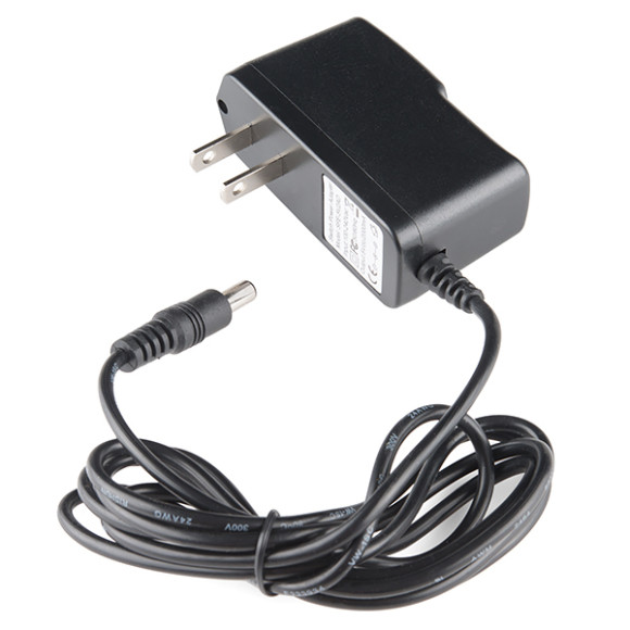
Option 1: The best way to power these RGB panels is using a 5V, 2A wall adapter with a 5.5mm x 2.1mm barrel jack, such as the one shown below, which is from Sparkfun.
The barrel jack goes to its receiver on the Arduino shield. This 5V is routed to the RGB panel through the power supply cable with the spade terminals that were discussed before. It also powers the Arduino Uno, when the shield is plugged into it.
Option 2: I also tested this RGB panel using a 1.5A, 5V wall cellphone/tablet charger with a standard USB-A connector and it worked just fine. In this case, you will use it to power the Arduino board, and RGB panel will receive the same power supply when the shield is plugged into the Uno board. You will need an appropriate USB cable suitable to the type of USB connector you have on your Arduino Uno board to connect the power supply from the wall charger. I am using Crowduino (Arduino Uno clone) board so the USB cable I would need is Type A Male to Mini B.
In part 3 of this tutorial, we will learn to install Adafruit RGB library and run some demo sketches on this 16×32 RGB LED panel.
Continue to Hookup Guide Part 3
|
|
