Hookup guide for 16×32 RGB LED panel – Part 3
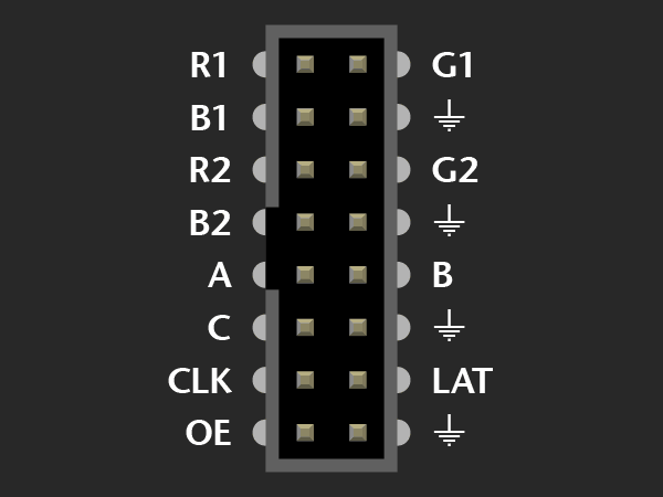
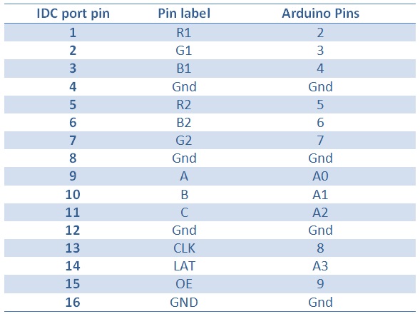
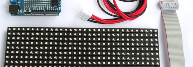
In this third part of the 16×32 RGB LED panel hookup guide, we will run some demo sketches with Arduino Uno to display basic text and animation on the 16×32 RGB LED matrix. These demo programs use Adafruit’s RGBMatrixPanel Library are found inside its Example folder. The wiring between the RGB panel and Arduino Uno is discussed in detail in the previous parts of this 3-part tutorial.
Click here to read Part 1 of this tutorial
Click here to read Part 2 of this tutorial
Click here to buy this kit from our US Tindie store
Get this RGB panel kit from our Elecrow store in China!
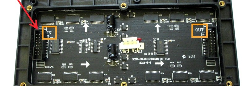
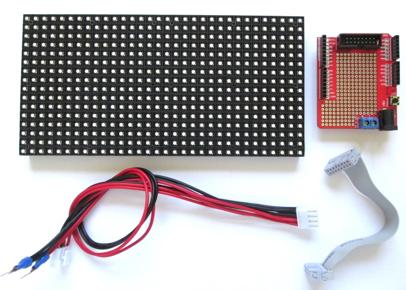
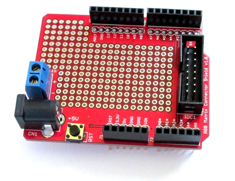
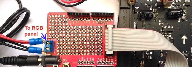
After wiring up the RGB panel to Arduino Uno through the connector shield, it’s time now to run some text and animation graphics on the RGB matrix panel. This would first require the following two libraries to be downloaded and installed.
Adafruit RGB Matrix Panel library
There are multiple ways of installing these libraries to your computer’s Arduino IDE tool. Please read this installation guide from Arduino website if you haven’t experienced it before. The RGB Matrix Panel library has built-in routines to illuminate selected pixels, construct line, rectangle, and circle, and print alphanumeric characters in two different font sizes.
After the succesfull installation of the above libraries, we can now try out some of the examples included in the library package. On Arduino IDE, load the testshapes_16x32 example from File→Examples→RGBmatrixPanel→testshapes_16x32 and upload to the Arduino Uno board. This example illustrates how to draw pixels, rectangles, and circles with chosen pixel color at specific locations. The program ends with printing some 5×7 pixel size text characters along two rows of the RGB panel. Power up the RGB panel and Arduino Uno and observe the program out in action.
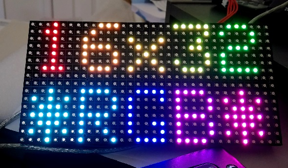
testshapes_16x32 demo output
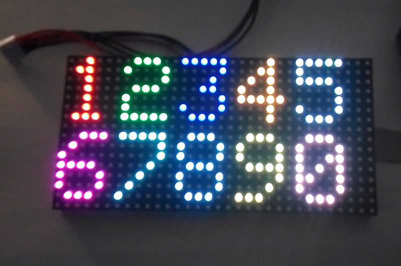
There are three more 16×32 RGB examples included in the library package: testcolors_16x32, plasma_16x32, and scrolltext_16x32. Because the Arduino pin assignments implemented in our RGB connector shield to connect the RGB LED panel match with the default setting of these examples, they can be just run by simply uploading to the Arduino Uno board.
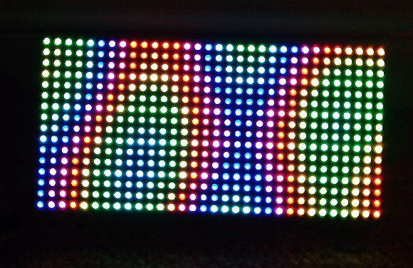
16×32 plasma demo
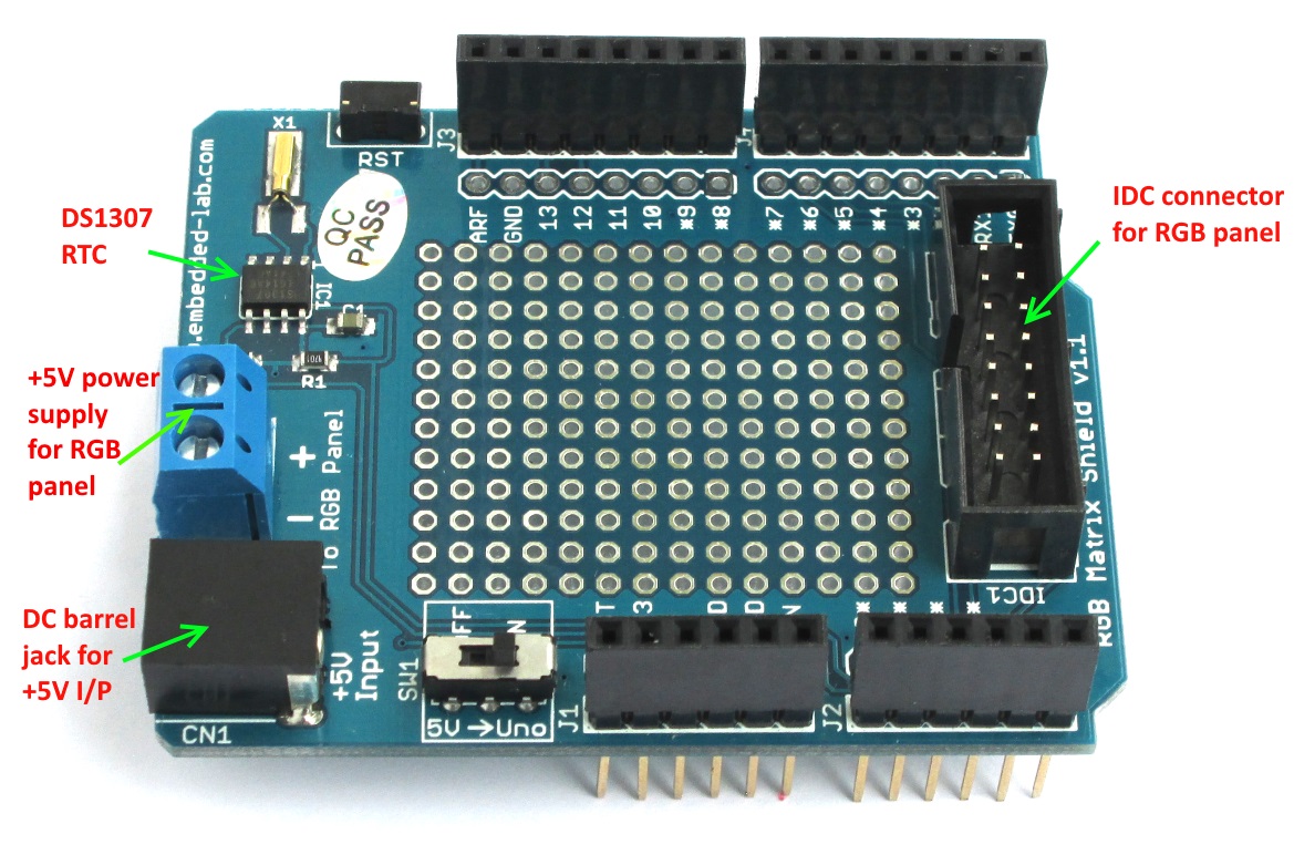
These RGB panels have unlimited applications. In my next article, I will write about constructing a colorful real-time clock display plus thermometer and hygrometer. Stay tuned!
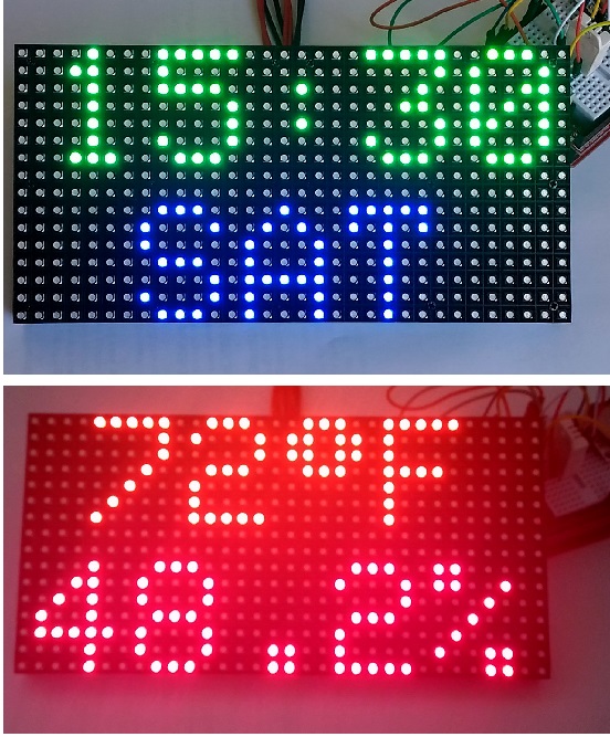
Real time clock and thermometer demo