In tutorial 3, we discussed how to use an SSD1306-driven I2C OLED screen with EasyESP-1 for displaying basic text and graphics. We used a 0.96″ (along the diagonal) 128×64 monochrome pixels OLED display for illustration. Despite its small size, the readability was pretty good due to its high contrast, which makes it a very good, compact size display for general applications. The excitement of having a display screen in an ESP8266 project can be further enhanced by upgrading the choice of display to colorful TFT LCD. One such screen that is readily available in the market at affordable price is ILI9341 based TFT LCDs. This tutorial describes the method to connect such displays with ESP8266 using Arduino IDE.

Interfacing an ILI9341 TFT LCD
Hardware
The datasheet of ILI9341 driver chip states:
ILI9341 is a 262,144-color single-chip SOC driver for a-TFT liquid crystal display with resolution of 240RGBx320 dots, comprising a 720-channel source driver, a 320-channel gate driver, 172,800 bytes GRAM for graphic display data of 240RGBx320 dots, and power supply circuit. ILI9341 supports parallel 8-/9-/16-/18-bit data bus MCU interface, 6-/16-/18-bit data bus RGB interface and 3-/4-line serial peripheral interface (SPI). The moving picture area can be specified in internal GRAM by window address function. The specified window area can be updated selectively, so that moving picture can be displayed simultaneously independent of still picture area.
You can find ILI9341-based TFT displays in various sizes on eBay and Aliexpress. The one I chose for this tutorial is 2.2″ length along the diagonal, 240×320 pixels resolution, supports SPI interface, and can be purchased for less than $10.
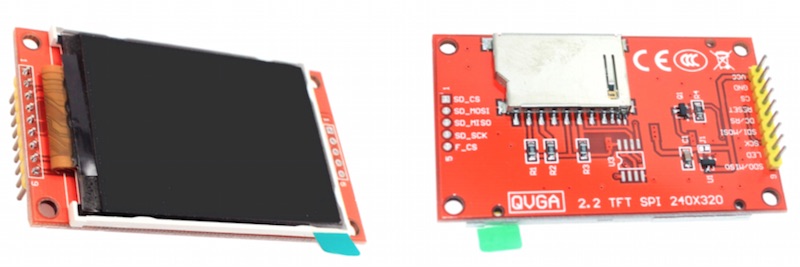
2.2″ TFT LCD used in this tutorial is bought from a Chinese store on Aliexpress
The connections between the TFT display and EasyESP-1 pins are as follows.
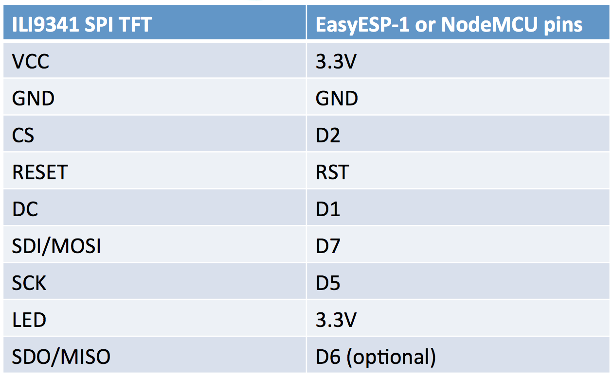
Connections between ILI9341 SPI TFT module and EasyESP-1
Note that we will be using the hardware SPI module of the ESP8266 to drive the TFT LCD. The SPI communication pins are multiplexed with I/O pins D5 (SCK), D6 (MISO), and D7 (MOSI). The chip select (CS) and Data/Command (DC) signal lines are configurable through software.
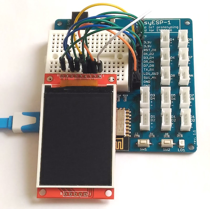
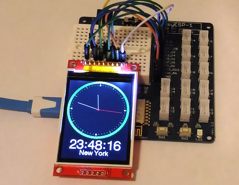
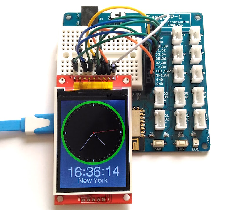
Complete setup of LCD on the EasyESP-1 breadboard
Software
For ILI9341-based TFT displays, there are some options for choosing the library for your application. The most common one is using Adafruit’s library for ILI9341 display. You will also need their GFX-library with this. There’s another one that I recently discovered named TFT ILI9341 ESP, and is more versatile than the Adafruit’s library. This is shared on github by Bodmer. We will use this library in this tutorial. So go ahead and download the TFT ILI9341 ESP library, and install it in your Arduino/libraries folder.
About this library (in Author’s words):
An Arduino IDE compatible graphics and fonts library for ESP8266 processors with a driver for the ILI9341 based TFT displays.
The library contains proportional fonts, different sizes can be enabled/disabled at compile time to optimise the use of FLASH memory. The library has been tested with the NodeMCU (ESP8266 based).
The library is based on the Adafruit GFX and Adafruit ILI9341 libraries and the aim is to retain compatibility. Significant additions have been made to the library to boost the speed for ESP8266 processors (it is typically 3 to 10 times faster) and to add new features. The new graphics functions include different size proportional fonts and formatting features. There are a significant number of example sketches to demonstrate the different features.
Configuration of the library font selections, pins used to interface with the TFT and other features is made by editting the User_Setup.h file in the library folder. Fonts and features can easily be disabled by commenting out lines.
As mentioned by the author, you need to open the User_Setup.h file inside the main library folder and modify the following two lines to match with our setup.
#define TFT_CS D2 // Chip select control pin
#define TFT_DC D1 // Data Command control pin
Now you are all set to try out tons of really cool built-in examples that come with the library. The following output corresponds to the TFT_Pie_Chart example.
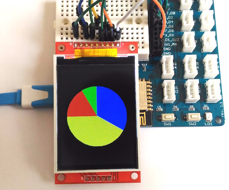
Drawing a colorful Pi Chart on TFT screen
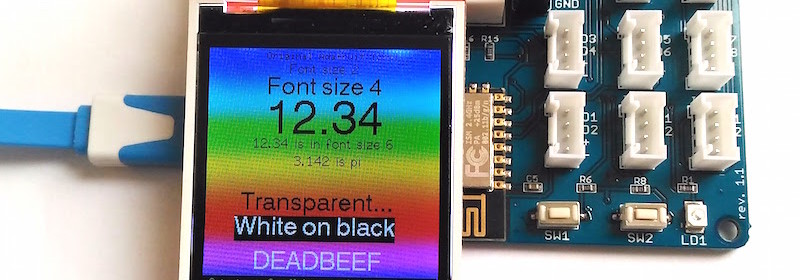
There is an example (TFT_Rainbow_one_lib.ino) for showing different size text fonts with rainbow colors in the background that looks pretty cool.
Rainbow colors demo
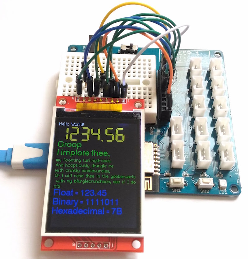
Another example of printing texts with different font sizes and colors
My favorite example is TFT terminal, which implements a simple “Arduino IDE Serial Monitor” like serial receive terminal for monitoring debugging messages from another Arduino or ESP8266 board.
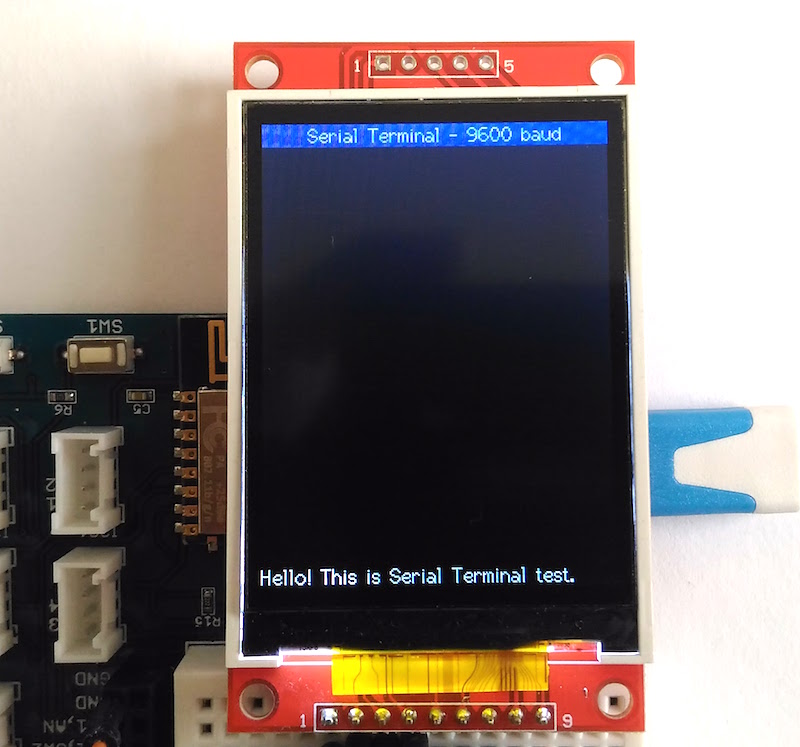
Serial receive terminal example
More tutorials