Tutorial 2: EasyESP-1 “Hello World” Example
After setting up the Arduino IDE to enable support for ESP8266, it’s time to write your first code for EasyESP-1 board. We will start with the classic hello world! example of electronics, a flashing LED. This is the best example to start with any new hardware platform as it gives us an opportunity to verify that the required software tools/drivers are installed properly and ready to rock.
Hardware Setup
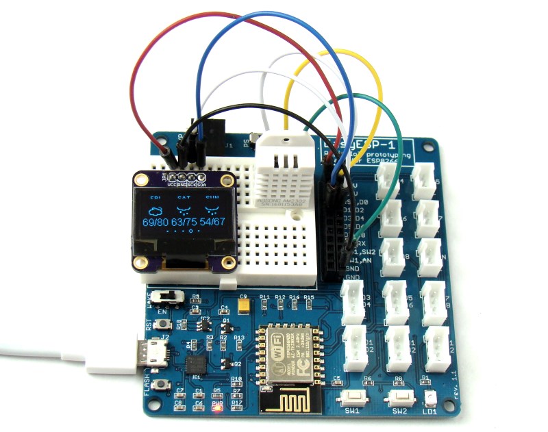
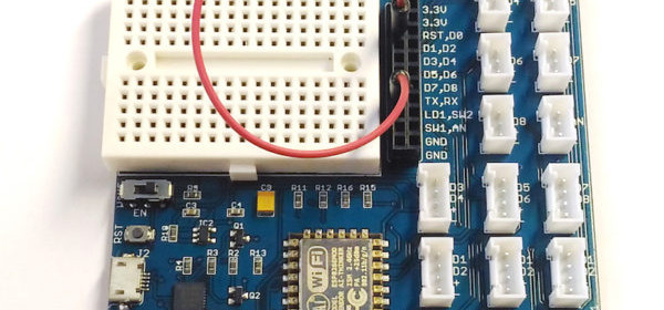
In this example, we will connect the LD1 and D1 pins of J3 header together with a jumper wire as shown below. This will connect the LD1 LED near the bottom right corner of EasyESP-1 to the D1 I/O pin (or GPIO5) of ESP8266.
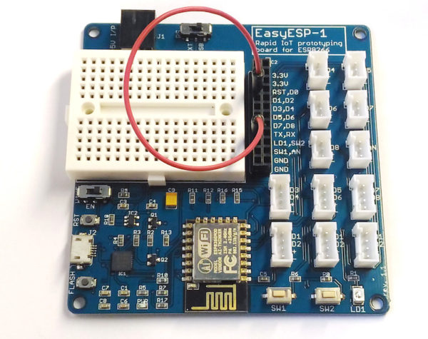
Connections for the “Hello World” example
Software
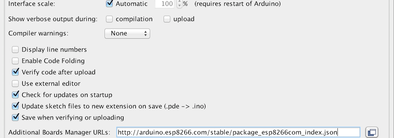
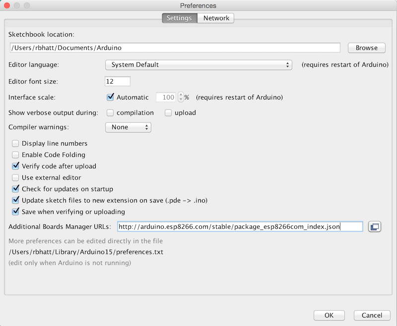
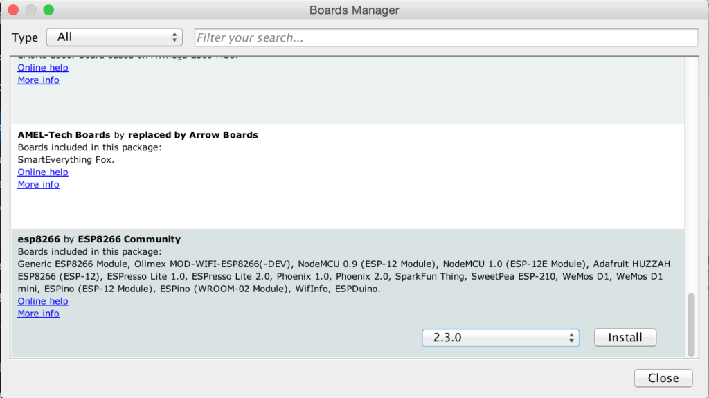
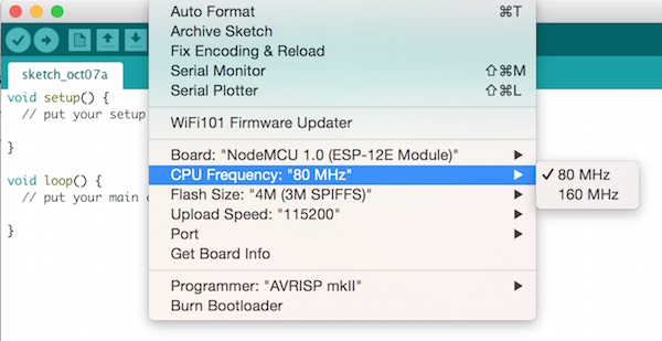
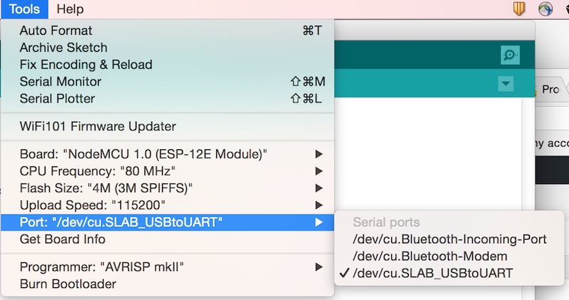
Open a new window on Arduino IDE and select appropriate options for Boards, Serial Port, CPU frequency, and Upload speed. You need to choose NodeMCU 1.0 (ESP-12E Module) from Board menu, set CPU frequency to 80 MHz, Upload Speed to 115200, and match Serial Port to the one that your EasyESP-1 is connected to. Check out my previous tutorial “Getting started with EasyESP-1 using Arduino IDE” for more details on this. Your selected options are shown in the bottom tab of the Arduino IDE, make sure they match with the ones shown below.
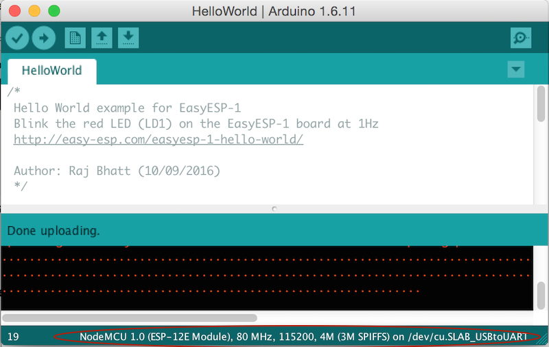
Arduino IDE option setup for EasyESP-1
As I described in the EasyESP-1 Introduction, EasyESP-1 uses the same I/O indexing as used by NodeMCU. This does not match with internal GPIO indexing. For example, pin D1 is actually mapped to internal GPIO5. In Arduino IDE, you can access this pin in both ways. For example, digitalWrite(D1, LOW) and digitalWrite(5, LOW) will both do the same thing, writes out logic ‘low’ to D1 pin. Next, copy the following code and paste it into your empty program window. The program is written to blink the LD1 LED at a rate of 1Hz. Save the code, verify it, and upload it to EasyESP-1 board in the same way as you do for Arduino.
/* Hello World example for EasyESP-1 Blink the red LED (LD1) on the EasyESP-1 board at 1Hz */ #define LD1 D1 // Define LD1 as D1 I/O pin // Alternatively, you can also define it as GPIO5 //#define LD1 5 void setup() { pinMode(LD1, OUTPUT); // Initialize LD1 as output } void loop() { digitalWrite(LD1, LOW); // Turn ON LD1 delay(500); // Wait for 0.5 sec digitalWrite(LD1, HIGH); // Turn it off delay(500); // Wait for 0.5 sec } |
Output
If everything worked perfectly, you would see LD1 flashing at 1 Hz and with 50% duty cycle (i.e. on and off time are both 0.5 sec).
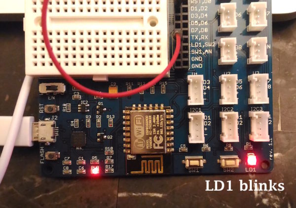
LD1 flashes at 1Hz rate