Author Archives: R-B

Upcycling a vintage film camera with Raspberry Pi

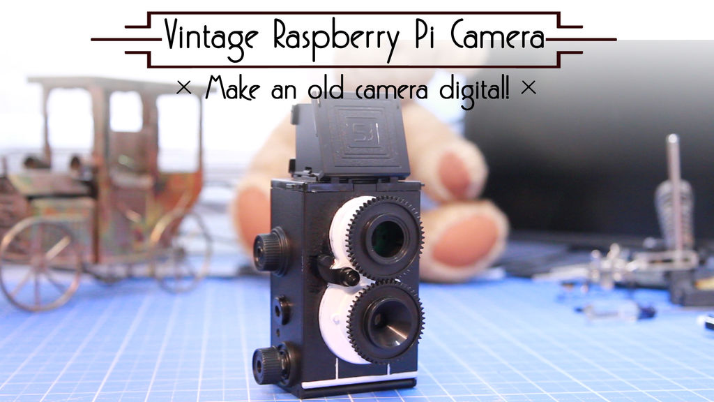
Gone are the days of vintage film cameras. If you still have one such camera lying around, you might want to consider upcycling it to a digital camera as a weekend fun project following this instrcutable. The author shows how to convert a 35mm twin-reflex film camera to digital using a Raspberry Pi zero with a camera module connected, a 1.8″ TFT LCD, and a rechargeable USB power bank. The camera also implement a push button for snapping pictures.

A vintage film camera turned digital using Raspberry Pi zero

A vintage film camera turned digital using Raspberry Pi zero

The hardware setup for this project is simple. The TFT LCD data and control pins directly connect to the I/O pins of the Pi Zero. The LCD screen fits into the viewfinder spot of the twin-reflex camera so that you can visually see the field of view of the camera lens while snapping shots. The instructable also describes a detail software setup process along with python scripts for controlling camera and uploading the pictures to user’s dropbox account via WiFi. If you love watching videos, the author has also posted the same instructions in a two-part video tutorial. The link to the first part is posted below:

Laser Sky Effect using Arduino

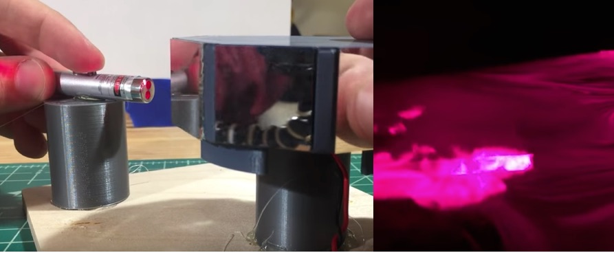
Bouncing a laser beam off a spinning mirror can create an amazing light show as illustrated in this Laser Sky video by Youtube channel Normal Universe. The spinning mirror sweeps out a laser plane, which illuminates the cross sections of smoke or fog in the room and let you visualize how the air medium is moving around you in a very cool way. The spinning mirror is built out of 8 pcs of tiny plane mirrors installed on an spinning motor assembly made of a PC fan and a 3D printed mount part. The Arduino Uno is used as the main brain in the project. It not only controls the power to the laser, but also monitors the speed of the spinning mirror with a closed loop feedback system made of an optical switch (basically made of an LDR and an LED). A 3D printed casing provides a nice look and adds safety to its operation.

Laser Sky effect using Arduino, laser pointer, and spinning mirror

Laser Sky effect using Arduino, laser pointer, and spinning mirror

Following video describes the build process in detail.

A DIY mono class D amplifier

The PAM8610 is a 10W stereo Class-D audio amplifier chip available in a 40pin QFN 6mm*6mm package. The PAM8610 runs off a 7V to 15V supply at much higher
efficiency than competitors’ ICs and requires a very few external components for operation. You can buy a PAM8610 amplifier breakout board for less than $2 on eBay and Aliexpress. This Instructables described how to use one of those amplifier modules along with a pack of rechargeable lithium battery to drive a 4″ speaker delivering ~15W of output power. The instructable describes also describes how to connect a charging circuitry for the lithium batteries for enabling charging through a universal micro USB charger.

A DIY class D mono audio amplifier

A DIY class D mono audio amplifier

This amplifier is a PAM8610, a dual amplifier capable of 15 watts per channel in a very small form factor which runs at 12v DC. As we are only going to use one output, we dont have to care about overheating issues (Anyways, the chip has high temperature detection, so even better).

In this step we only are going to solder the aux port to the board with two wires. The middle lead of the aux port is usually GND, so connect it where it says GND on the amplifier board (should be very close to the left and right channel inputs on board). Then conect either lead of the aux input to either channel input on the board. If you feel, you can solder some wires to the power in on the board (where it says +12v and gnd).


Making an Ultrasonic Anemometer

An anemometer is a common instrument at a weather station. It is used to measure the wind speed and wind direction. The most common type of anemometer uses mechanical sensors consisting of three or four hemispherical cups mounted on horizontal arms on a vertical rod. As the wind blows, the cups are pushed causing the arms to rotate at a rate proportional to the wind speed. In addition, a wind vane connected to the anemometer can give the direction measurements. While the cup and vane anemometers are very popular due to their very simple design, they can be susceptible under cold and humid conditions because of their mechanical rotating parts, possibly causing the turbine to stop operating during extreme conditions. Designed without any moving parts, the ultrasonic anemometers are more reliable, maintenance free, long-lasting, and can operate in challenging weather conditions. In this article, we will review the basic working principle of an ultrasonic anemometer, and discuss about some DIY versions of ultrasonic anemometers reported by makers on the internet.

Working principle of ultrasonic wind sensor

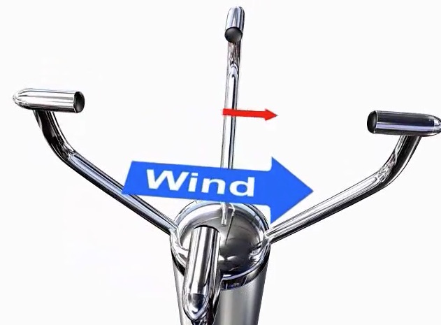
A typical ultrasonic anemometer consists of 2 pairs of ultrasonic transducers mounted at right angles to one another as shown in the figure below. Each sensor is capable to transmit and receive ultrasonic pulses. The physical distance between the opposite facing sensors is fixed and known. During operation, the time taken for an ultrasonic pulse of sound to travel from the North (N) transducer to the South (S) transducer is compared to the time for a pulse to travel from S to N transducer. If there were no wind blowing, the two times should exactly match. Otherwise, the sound wave traveling with the wind should arrive earlier than the sound traveling against it. For example, if there is a wind blowing to N, the N to S travel time would be more compared to the S to N travel time. The difference in the time of flight can give the relative speed of wind along NS axis. Similarly, flight times are also compared along the East-West and West-East directions to compute the wind velocity along the EW axis. The two rectangular velocity components of the wind are then combined to compute the wind vector with a resultant sum and an angle of wind velocity. The sensor arrangement shown below gives only the horizontal wind speed. Measuring a three dimensional wind speed requires sensor arrangements along the vertical direction too.

Basic layout of an ultrasonic anemometer

Basic layout of an ultrasonic anemometer (Source: http://gillinstruments.com/products/anemometer/principleofoperation2.html)

DIY Ultrasonic Wind Sensors

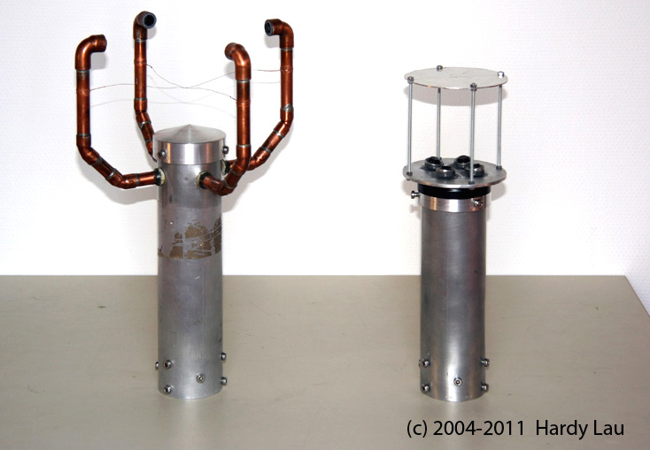
Among hobbyists and DIY community, the cup-based mechanical sensor is the most popular choice for homemade anemometers. There are also a few resources available online to make ultrasonic anemometers. The oldest report that I could find on the internet is from Hardy Lau (Germany). He made two different prototypes of ultrasonic anemometers. His first design consist of four ultrasonic transducers arranged to perform measurements along two orthogonal directions, just like we discussed above. The distance between the opposite transducers is approximately 21 cm. It is capable to measure the horizontal components of the wind speed (up to 45m/sec with a resolution of 0.05m/sec) and the wind direction at 1º resolution. The design implements a heating mechanism utilizing four BD743 power transistors and dummy resistive loads to heat the sensors and the enclosing metallic body during extreme winter conditions to ensure that the sensor operation is not affected by snowfall and possible ice formation. The Microchip dsPIC 30F4012 processor is used to do all the control functions and computation tasks involved in processing the transducer outputs. The wind speed and direction data are available for data logging through a serial interface.

Hardy Lau's homemade ultrasonic anemometers

Hardy Lau’s homemade ultrasonic anemometers

His second prototype is a more advanced and aerodynamically more favorable design with minimum interference with wind, thereby resulting in less turbulence. Opposite facing transducers alternately sends and receive ultrasonic pulses to each other via a top sound reflecting plate, and are processed by the dsPIC33FJ128MC802 processor. For the full detail of the project, visit Hardy Lau’s anemometer page.

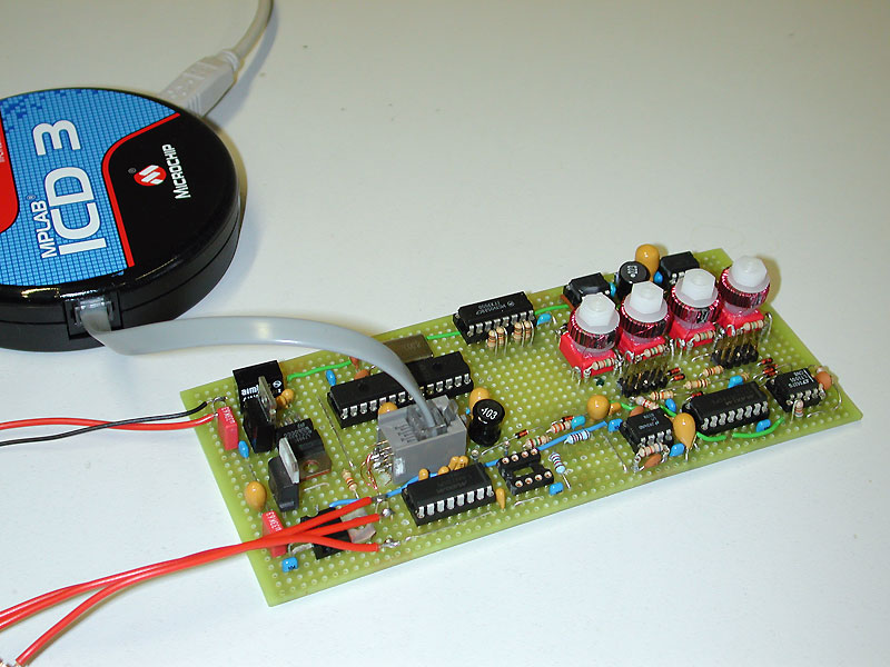
Control circuit board

Hardy Lou’s control circuit board

Another successful DIY design of an ultrasonic anemometer is from Carl47. His design of the sensor is similar to Hardy Lou’s first version. Carl47 implemented the phase shift method for a precise measurement of the flight times, and uses Atmega328 for processing the sensor data. You can download the full project report from the following link.

https://mysudoku.googlecode.com/files/UltrasonicAnemometer.zip

The most recent design of a DIY ultrasonic anemometer published online is by Lukas Fassler from soldernerd. He has a series of posts about his anemometer project that can be accessed here:

https://soldernerd.com/arduino-ultrasonic-anemometer

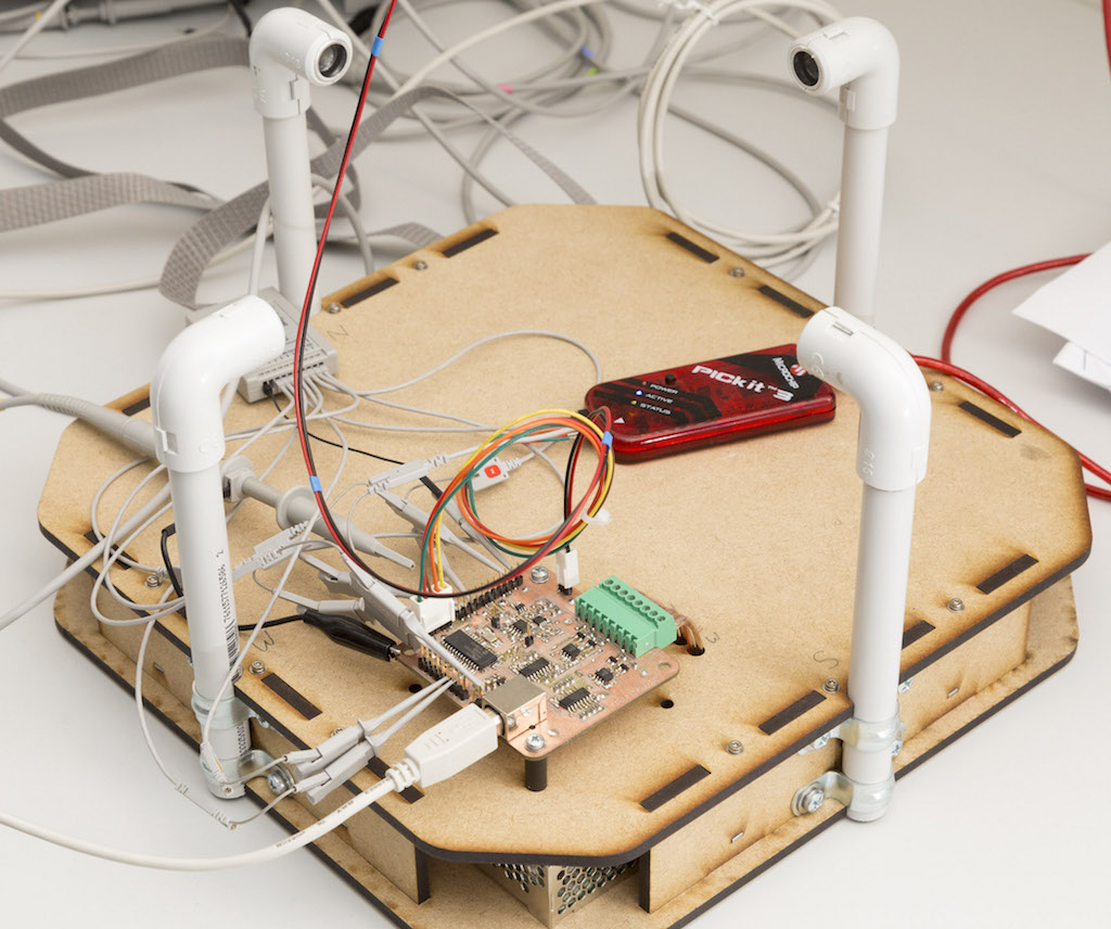
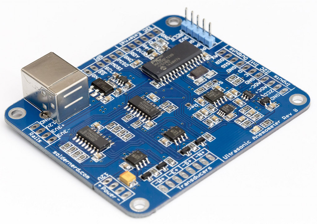
The sensing part is pretty much similar to the earlier two designs we discussed. But Lukas has designed a couple of different varieties of control board for his setup. He has one in the form of an Arduino shield and another one as a standalone board using a PIC32 processor. He even built a tiny wind tunnel using a brushless motor fan for testing his sensor. His series of tutorials on building an ultrasonic anemometer are worth reading.

Lukas

Lukas Fassler’s ultrasonic anemometer setup

PIC32

Lukas’s PIC32 based standalone ultrasonic anemometer controller

If you know any other resources on DIY ultrasonic anemometers, please let us know. You can email us at admin (at) embedded-lab.com.

Making a simple weather web server using ESP8266 and BME280

Since its launch in 2014, ESP8266 has revolutionized the IoT space by offering an extremely cost-effective and programmable WiFi-enabled microcontroller to hobbyists and professionals, thereby opening the doors to all kinds of everyday objects and sensors to the internet. In addition, with it’s built-in WiFi capability, the ESP8266 can also serve as a standalone web server on a local network, and can respond to the http GET commands received from an internet browser. This project illustrates how to construct a simple standalone weather web server utilizing NodeMCU development board for ESP8266 and Bosch’s BME280 environmental sensor chip. On receiving the web requests, the ESP8266 responds back by returning back an HTML webpage containing the ambient temperature, humidity and pressure measurements. With the help of refresh meta tags, the webpage automatically reloads every 15 seconds to get the latest environmental sensor data.
Weather web server using ESP8266 and BME280 environmental sensor

Weather web server using ESP8266 and BME280 environmental sensor

Hardware

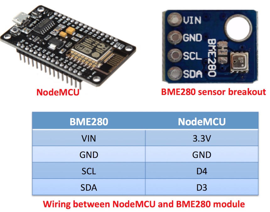
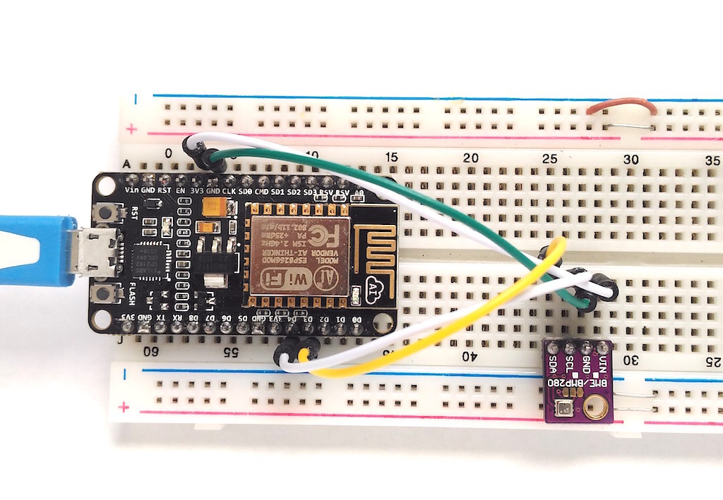
This project requires minimal hardware components. You will need an ESP8266 development board, like NodeMCU that I am using here, a BME280 sensor module, a breadboard with some jumper wires, and a USB cable for programming the NodeMCU board.

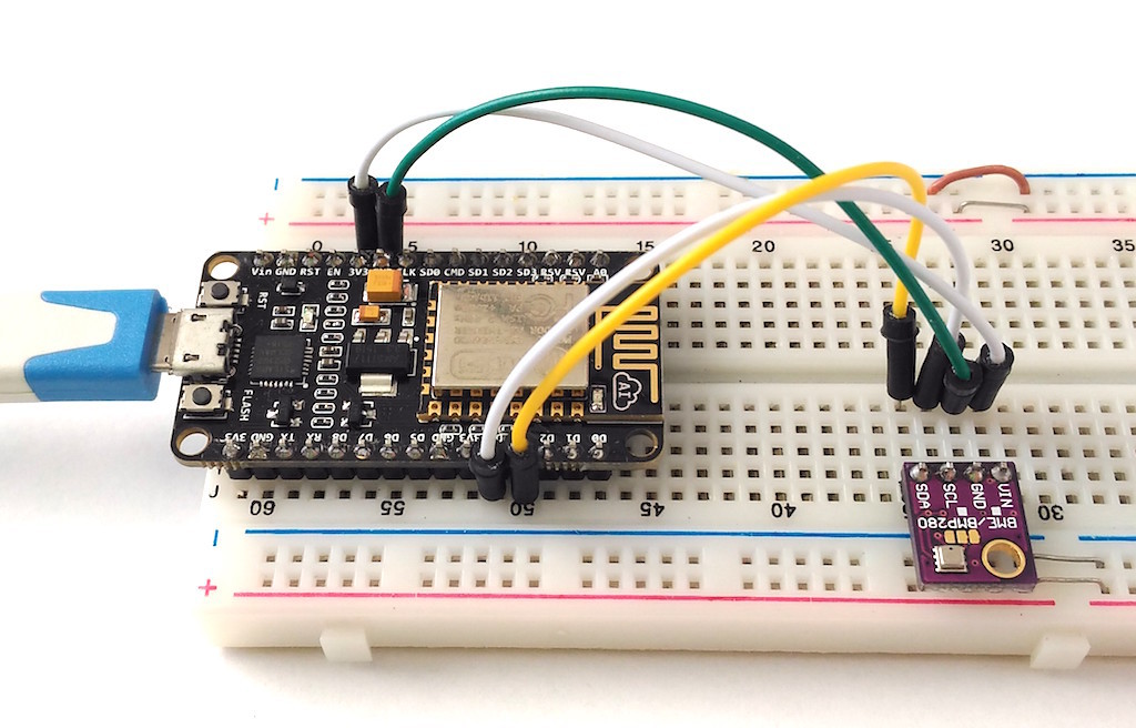
BME280 is a fully integrated environmental unit from Bosch that combines sensors for pressure, humidity, and temperature in a tiny 8-pin metal-lid LGA package of size 2.5 x 2.5 x 0.93 mm³. Because of its compact size, ease of use (BME280 supports standard I2C and SPI interfaces), and availability of supporting open-source Arduino libraries, BME280 is very popular among weather enthusiasts. In this project, the I2C data (SDA) and clock (SCL) pins of the BME sensor module are connected to the NodeMCU pins D3 and D4, respectively.
setupserver

Weather web server setup on breadboard

Weather web server hardware setup on breadboard

Software

The ESP8266 firmware for this project is developed using Arduino IDE. You need to install the ESP8266 core to enable the Arduino IDE for ESP8266 programming. Instructions can be found in the ESP8266 core github page or here too. You will also need the following Adafruit libraries for reading data from the BME280 sensor.

Adafruit unified sensor library

Adafruit BME280 library

The I2C address for BME280 is hardcoded in the Adafruit_BME280.h file (look for the line #define BME280_ADDRESS  0x77) inside the Adafruit_BME280_Library folder. Adafruit’s BME sensor modules are hard-wired to use the I2C address of 0x77. But the BME280 can have a slightly different I2C address (0x76) if its external SDO pin is grounded. If you are using the sensor modules from other party, it is likely that it’s address would not match with the default value in the Adafruit library. For example, for most of the BME280 sensor modules available on eBay or Aliexpress, I have found their I2C address to be 0x76. So, if you didn’t get any response from the sensor using the default address set in the Adafruit_BME280.h file, you might need to change that to 0x76.

My complete code for this weather webserver project can be downloaded from the following link:

Download BME280_webserver_code

The code for a very basic HTML webpage with sensor output and auto refresh meta tag is included in the above ESP8266 firmware. Note that you need to edit the SSID name and password in the program to match with your WiFi network before uploading it to the NodeMCU board.

Output

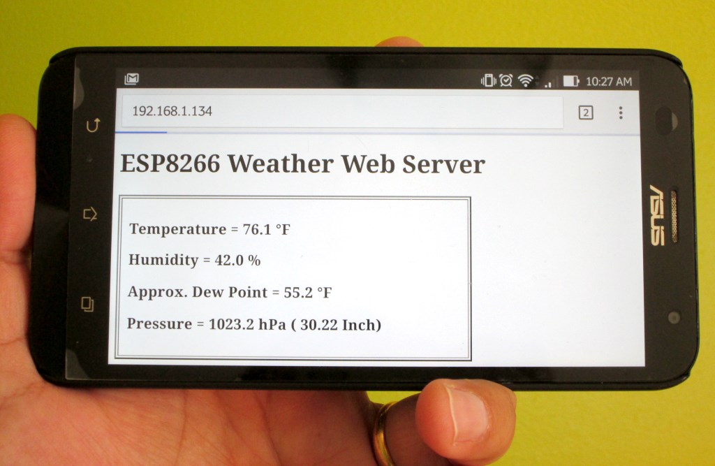
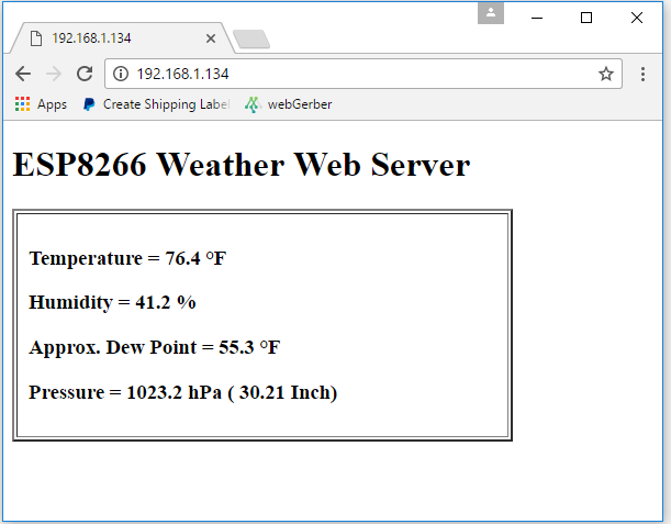
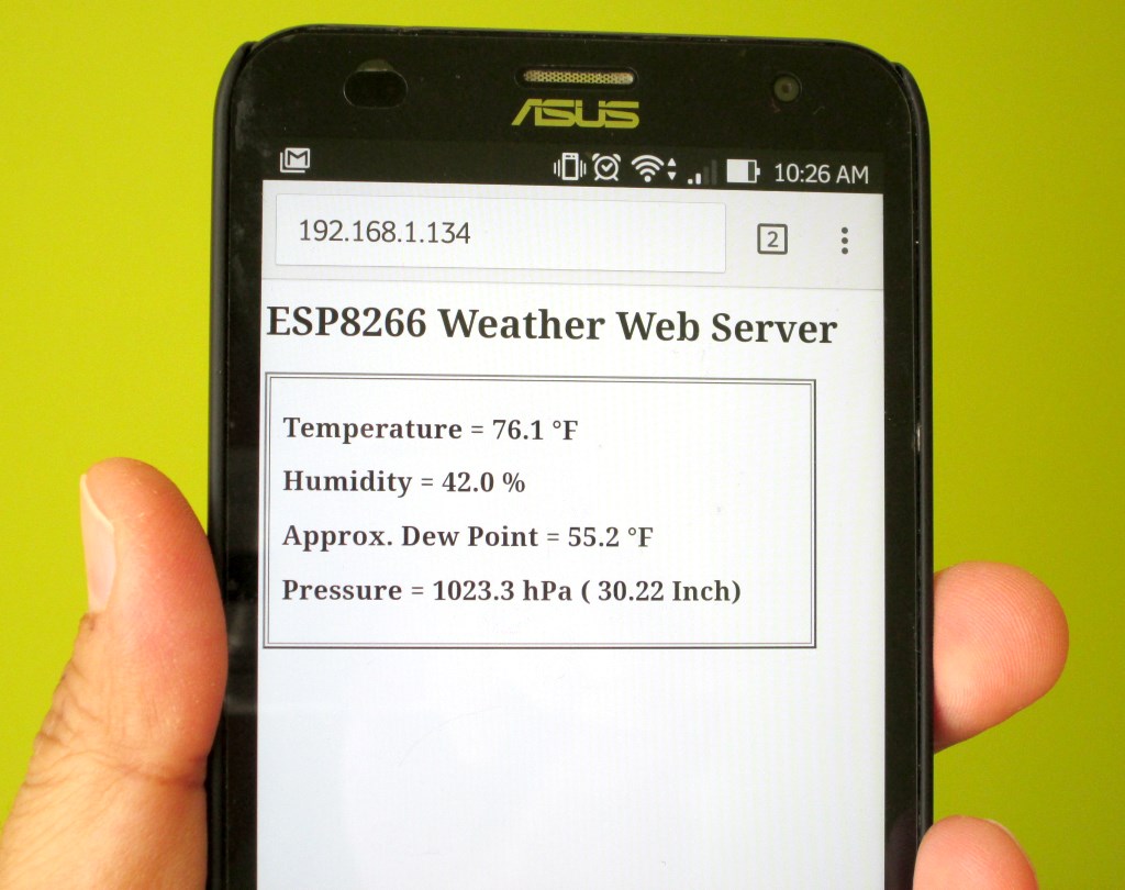
After uploading the program to NodeMCU, when the ESP8266 restarts it prints out on the serial monitor the IP address it’s allocated in the local network. In order to access the ESP8266 web server, you need to open a web browser on any computer, tablet, or smartphone connected to the same WiFi network and type in the ESP8266 IP address in the URL field and hit enter. On receiving a client request, the ESP8266 serves a webpage containing the BME sensor readings, as shown below.
Standalone weather web server using ESP8266 and BME280

Standalone weather web server using ESP8266 and BME280

The HTML page is refreshed automatically every 15 second to get the latest sensor readings. The Dew Point is computed from temperature and humidity using the following approximation:

Source: Wikipedia
Source: Wikipedia

Weather web server broadcasting BME sensor readings

Weather web server broadcasting BME sensor readings

This is a very nice and handy way of monitoring the weather around us, as it allows to watch the environmental parameters on our tablets and smartphones that we are carrying all the time.
Smartphone

Weather data on smartphone

Acknowledgement

Thanks to Rui Santos from Random Nerd Tutorials for sharing his DS1820-based temperature web server code. I modified his code to incorporate the BME280 sensor readings, and also added auto-refresh Meta tag to reload the HTML page automatically in every 15 sec.

« Older Entries Recent Entries »