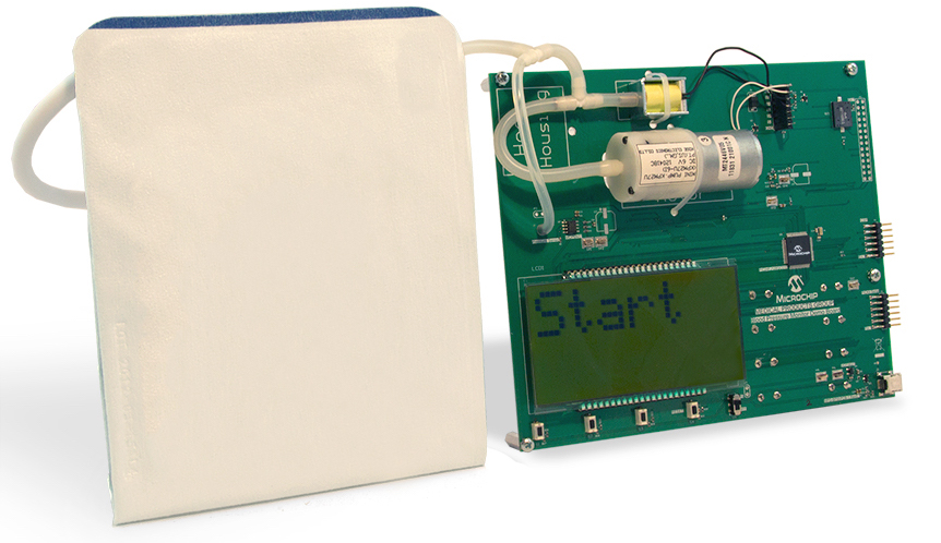
Digital blood pressure monitors come in handy for checking and monitoring blood pressure at home or in a hospital. This reference design from Microchip provide tips to build a low-cost, low-power, handheld or portable blood pressure meter with user interface using the system-on-a-chip PIC24FJ128GC010 MCU. The meter is used with an inflatable cuff for restricting blood flow and a pump to inflate the cuff, and measures both systolic and diastolic pressures, as well as the heart rate of the patient.
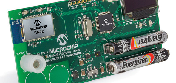
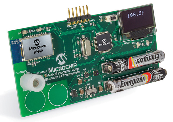
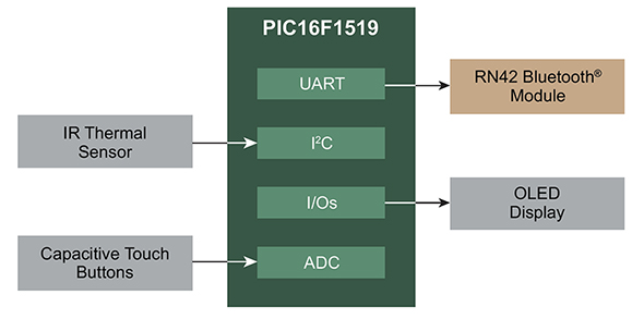
Bluetooth connected thermometers are making their way into many consumer products such as fitness devices, medical activity trackers, BBQ Grills, etc, to allow temperature monitoring through smartphones and tablets. This reference design from Microchip illustrates the implementation of a Bluetooth-connected digital thermometer using Microchip’s PIC16F1519 MCU and RN42 Bluetooth Module.
Bluetooth connected thermometer reference design
Powered by two AAAA batteries, this design measures temperature in Fahrenheit or Celsius using the Melexis MLX90614 non-contact infrared thermometer sensor. It also implements input touch buttons using mTouch integrated capacitive touch technology. An OLED display on board is used to demonstrate stand-alone design capability, while the Bluetooth module demonstrates smartphone/tablet connected design capability. This reference guide therefore provides useful tips to design a low-cost wireless digital thermometer that can be handheld or integrated into a wearable device.
Solar panels collect energy from the sun and convert it to electricity. Because the sun is not consistent throughout the day, the output power from the solar cell is also not constant. MPPT stands for Maximum Power Point Tracking and is an electronic system for solar panels that allows them to produce and deliver maximum available power. In a solar-powered battery charging system, it is done by varying the ratio between the voltage and current delivered to the battery. For instance, if there is excess power harvested from the panels during high Sun conditions, the MPPT converts it to additional current to charge the battery much faster.
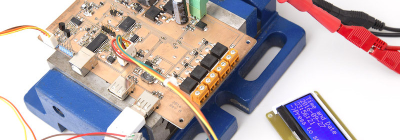
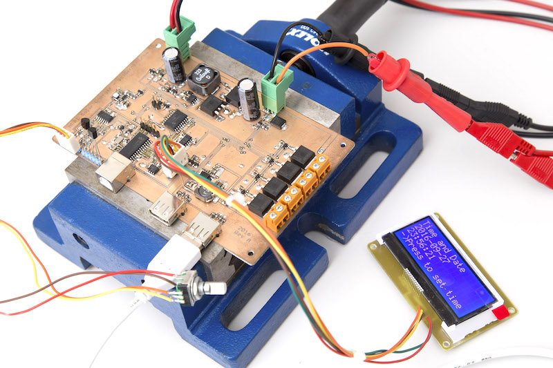
MPPT Solar charger using PIC MCU
LUKAS FÄSSLER shares his design of PIC MCU based MPPT charge controller along with his latest test results. He used a MCP3424 4-channel 18-bit ADC for accurate measurements of the input and output voltages and currents, which are key parameters for tracking the maximum power condition.
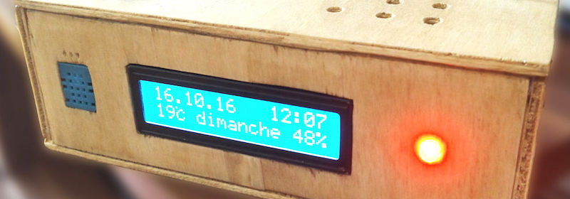
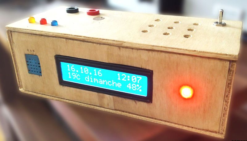
This multifunctional Arduino clock does more than just showing time. Besides displaying time, date, and day of the week, it also measures the ambient temperature and humidity, runs disco LED lights with music, and has a built-in speaker to hook an audio source like a mp3 player.
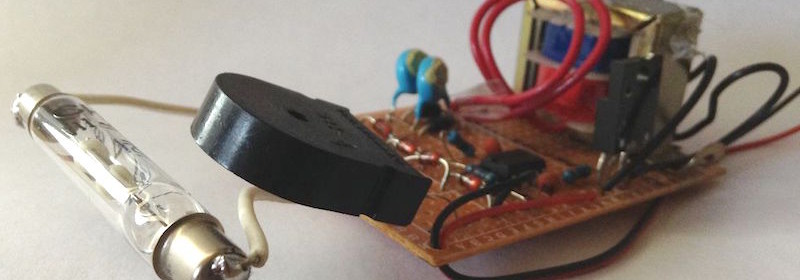
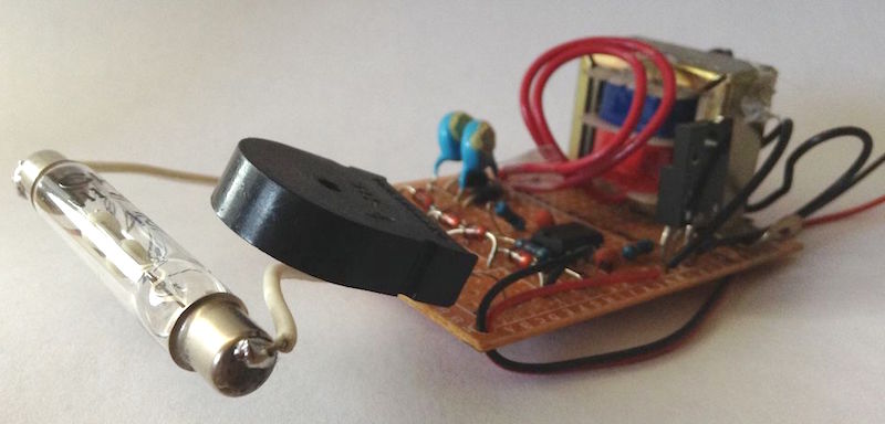
Geiger counters are used to detect beta particles and gamma rays radioactive emissions. The counter consists of a tube filled with an inert gas such as helium, neon, or argon at low pressure, to which a high voltage is applied. The tube becomes conductive of electricity when it is impacted by a high-energy particle or photon. Tanner_Tech‘s Instructable shows how to build the simplest 555 timer based DIY Geiger counter using minimal electronic components.
Geiger counter using 555 timer
Tanner_Tech‘s design uses 555 timer IC as an astable multivibrator to drive a step-up transformer through a MOSFET in order to generate the high voltage required for the Geiger tube. A piezo element placed in series with the Geiger tube acts as a detector, which clicks every time the ionization event occurs inside the tube due to high energy particles.
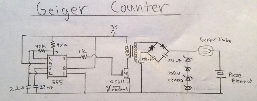
Circuit diagram of 555 timer based Geiger counter
Following video shows this device working.
Too make this Geiger counter work, there needs to be two parts of this circuit; the high voltage power supply, and the detector circuit. In the diagram above, the high voltage circuit consists of a 555 timer driving oscillator driving a transformer. The 555 timer generates a square wave that, through a resistor, turns on and off a MOSFET transistor. This MOSFET drives a small step up transformer. The output of the transformer is then fed into a voltage doubler where the voltage is boosted to about 500 volts. Then, the voltage is regulated through a series of 4 100v zener diodes to the Geiger tube’s recommended 400 volts.
For the detector circuit, the Geiger tube’s anode is wires directly to the 400 volt power supply. In between the cathode of the tube and ground, I placed a piezo electric element. This converts the small current flow from the Geiger tube to a audible click.