Nocturnal hypoglycaemia detector
Hypoglycaemia is a condition characterized by an abnormally low level of glucose in blood. It is associated with diabetes, and is likely to occur if someone with diabetes takes too much insulin, eats less than usual, or exercises too hard. Novirium‘s Nighttime Hypoglycaemia monitor is a bluetooth-enabled device that acts as a safety net for type 1 diabetics, while they’re sleeping. The nighttime hypoglycemia results in excessive sweating. This monitor measures the skin temperature and humidity to detect severe nocturnal hypoglycaemic events. Measurements are taken periodically and are sent to a nearby Android phone via Bluetooth. If such an event is detected, a list of emergency contacts are called for assistance.
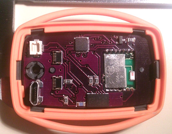
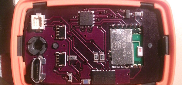
Nighttime hypoglycemia monitor
A mobile sensor device contains an ATmega328p, an HIH6131 humidity and temperature sensor, a LIS3LV accelerometer and a SPBT2632C2A Bluetooth module, all powered by a 2.7V LTC4081 switchmode power supply/charger and a 400mAh LiPo battery. The sensor is designed to be worn close to the skin of the diabetic, and detect the heavy sweating that often occurs with very low blood glucose levels.
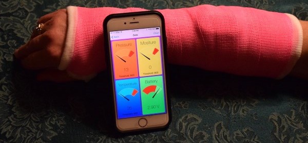
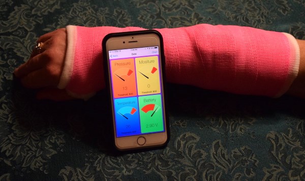
Every 15 minutes, the sensor module powers up the Buetooth module and connects to the nearby Android phone, uploading all the sensor data for that period before switching the Bluetooth back off to save power. The Android application then sorts through this data, and determines if an alarm is required. If an alarm is triggered, it then works through a list of preset contacts, calling them for assistance until one texts back.