Author Archives: R-B

Lab 10: DC motor interfacing to PICMicro
Description

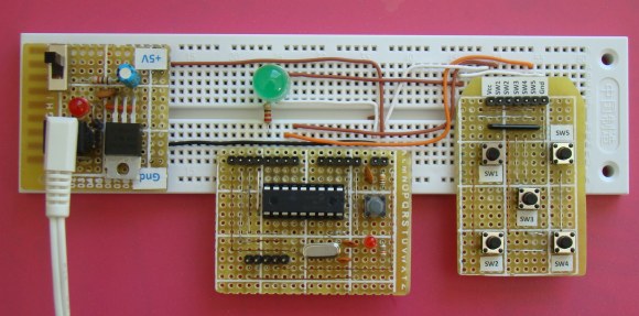
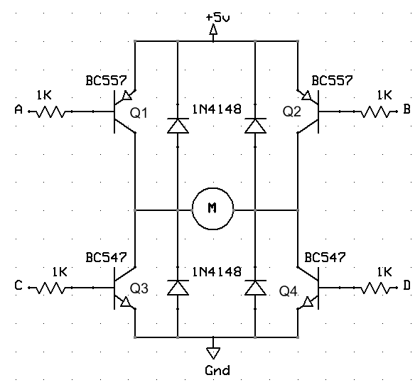
Perhaps one of the most entertaining things to do with an embedded microcontroller is to get it to actually move something. Three very popular devices used to “make things move” include dc motors, RC servos, and stepper motors. This lab session will look at how you can interface a dc motor to a PIC microcontroller.

Required Theory

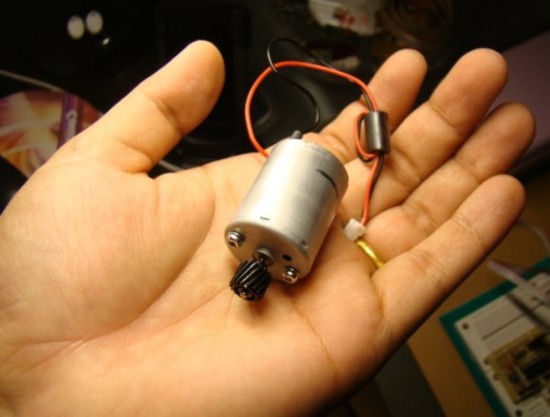
DC motors are simple two-lead, electrically controlled devices that convert electrical power into mechanical power through the interaction of two magnetic fields. One field is usually produced by a stationary permanent magnet (on the stator), and the other field is produced by an electric current flowing in the motor coil (on the rotor). The interaction of the two fields results in a torque that tends to rotate the rotor. For this experiment, a reversible, permanent magnet, brushed DC motor is selected. The term ‘reversible’ means the rotation of the motor can be reversed by simply flipping the terminals of the DC power supply. One such motor is shown below. I got it from my old broken printer. The dc motors are found in CD players, toy cars, cassette player, printers, etc.
Read more

Programmable digital timer switch using a PIC Microcontroller

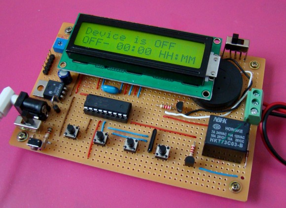
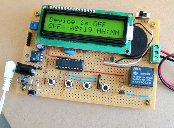
Digital timer switches are used to control the operation of electrical devices based on a programmed schedule. This project describes a programmable digital timer based on the PIC16F628A microcontroller that can be programmed to schedule the on and off operation of an electrical appliance. The appliance is controlled through a relay switch. This timer switch allows you to set both on and off time. That means, you can program when do you want to turn the device on and for how long you want it to be remained on. The maximum time interval that you can set for on and off operation is 99 hours and 59 minutes. The project provides an interactive user interface using a 16×2 character LCD along with 4 push buttons.

Programmable digital timer

Note: (June 30, 2016) A revised version of this project with added new features is posted here.

Circuit Design

The circuit diagram of this project is shown below. A 5V relay is driven by a PN2222 transistor that is controlled by RB3 pin of PIC16F628A. Digital inputs from the 4 push buttons are read through port pins RA2, RA3, RA4, and RB0. The functions of these push buttons are discussed in the operation section below. A standard 16×2 character LCD is used in the project to display the device status, program menu and time. The LCD is operated in 4-bit mode, therefore, only 6 I/O pins of PIC16F628A are required to drive it. A piezoelectric buzzer provides audible tone when the timer is started and stopped. It also beeps when the device is turned on or off. The + 5V power supply for the circuit is derived from a LM7805 regulator IC. The input to the regulator is given from a 9V DC wall adapter.

Read more

Lab 9: Pulse Width Modulation (PWM) using PIC CCP module

Description

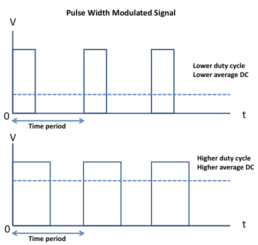
Pulse width modulation (PWM) is a technique of controlling the amount of power delivered to an electronic load using an on-off digital signal. The fraction of the period for which the signal is on is known as the duty cycle. The average DC value of the signal can be varied by varying the duty cycle. The duty cycle can be anywhere between 0 (signal is always off) to 1 (signal is constantly on). Suppose, if the signal has +5 V while it is on and 0 V during off condition, then by changing the duty cycle of the signal, any voltage between 0-5 V can be simulated. This method is commonly used for controlling speeds of DC motors and brightness of lamps. This lab session will talk about how to generate a PWM signal using the PIC16F628A microcontroller and control the brightness of an LED with it. PIC16F628A has a built-in hardware, called Capture/Compare/PWM (CCP) module, to generate a PWM signal.

Read more

Motion detection alarm using a PIR sensor module with a PIC Microcontroller

Introduction

This project describes a motion sensor alarm based on a Passive Infra-Red (PIR) sensor module. There are many vendors that manufacture the PIR sensor modules and almost all of them are pretty much the same in function. They have a single output that goes high (or low, based on specification) when the motion is detected. In this project, a PIC12F635 microcontroller continuously monitors the output from the sensor module and turns a buzzer on when it goes active.

Theory

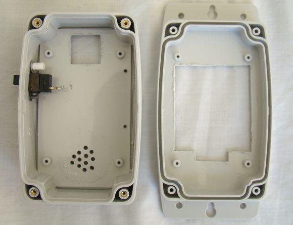
Certain crystalline materials have the property to generate a surface electric charge when exposed to thermal infrared radiation. This phenomenon is known as pyroelectricity. The Passive Infra-Red (PIR) sensor module works on the same principle. The human body radiates heat in the form of infrared radiation which is maximum at about 9.4 um. The presence of human body creates a sudden change in the IR profile of the surrounding that is sensed by the pyroelectric sensor. The PIR sensor module has an instrumentation circuit on board that amplifies this signal to appropriate voltage level to indicate the detection of motion.

Read more

Lab 8: Asynchronous serial communication

Description

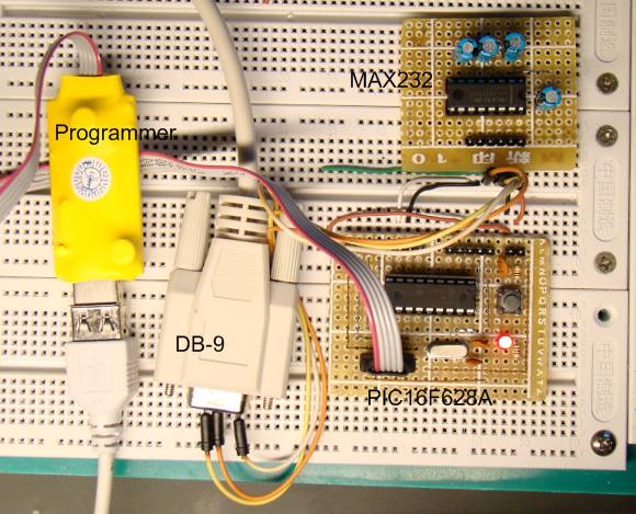
The PIC16F628A microcontroller has a built in Universal Synchronous Asynchronous Receiver Transmitter (USART) hardware that allows to communicate with a wide range of serial devices such as memory chips, LCDs, personal computers, etc. The USART module has two modes of operation: synchronous (requires a synchronized clock between the transmitter and receiver) and asynchronous (no synchronization clock required). As the asynchronous mode is more popular, we will focus today’s lab session on this and will establish a two way serial data link between the PIC microcontroller and a PC.

Required Theory

Serial communications are used in microcontroller-based systems, mostly due to the scarcity of available I/O pins. Besides for long distance communications, serial data transfer is more simple and cost effective as the required hardware connections in the data link can be reduced to three (Tx, Rx, and Gnd).
Read more

« Older Entries Recent Entries »